Oct 14, 2026
Cut C-cores are a geometry decision, not a brochure upgrade
When a high-frequency transformer or inverter stage outgrows a closed toroid—thick foil, bobbin tooling, serviceable windings, or a deliberate gap—engineers reach for cut C-cores. Iron-based nanocrystalline cut C-cores sit in that niche: Bs in the ~1.2 T class, low loss at tens of kHz, and a C-shaped stack that opens for winding and reassembly. The failure mode is not “forgot nanocrystalline.” It is freezing gap length, cut-face finish, AL under your volt-seconds, and winding keep-outs from fringing before a China OEM builds a second-source lot that only matches outer envelope.
This article is for service-over-price OEMs in JP, CA, US, FR, UK, IT, RU, and similar markets who already run VAC Vitroperm-class or Hitachi Metals Finemet-class nanocrystalline programs and need a drawing-matched China partner—not a catalog “C-core” with brochure μ. Dongguan JH Amorphous Co., Ltd. (www.amorphousoem.com) supplies OEM/ODM nanocrystalline and amorphous cut cores under ISO9001:2015 and IATF 16949. Product context: nanocrystalline cut C-cores for power magnetics and the family page nanocrystalline C-cores.
Cut and coated cores — gap and finish belong on the drawing with AL.
What a nanocrystalline cut C-core actually is
A cut C-core starts as wound nanocrystalline ribbon (Fe-Si-B-Nb-Cu class and related), annealed for the magnetic grade, then cut into mating C halves (or multi-cut stacks) so the winding window opens. Typical finished-part conversations cite Bs ~1.20–1.25 T class, Curie near ~570°C, stacking factor around ~0.8, ribbon thickness often ~12–25 μm, and assembly windows commonly discussed about -40°C to +140°C—limited by coating, varnish, and copper more than alloy Curie. Cut faces create one or more intentional air gaps (or near-butt joints with shim control). That gap is the design feature: it sets effective μ, stores energy if you need it, and defines the fringe field your first turns must respect.
Do not confuse cut C transformer cores with high-μ closed-path CMC toroids. Anneal philosophy, AL vs bias honesty, and loss density targets differ. Mixing roles by OD alone is the same μ trap already covered for CMC vs inductor grades—see the μ trap on nanocrystalline datasheets.
When cut C-cores win vs when a toroid still wins
Decision factor
Favor cut C-core
Favor closed toroid
Winding method
Bobbin, foil, multi-section HV, reworkable coils
Toroidal winding OK; low turn count; closed path preferred
Gap / energy storage
Discrete or shimmed gap needed for L under bias
No gap; magnetizing inductance for transformers / CM
Service / assembly
Open halves for potting, insulation build, field service
Once wound, closed; lower leakage if well canceled
Leakage / EMI
Expect more leakage and fringe; plan shields/keep-outs
Tighter flux containment for CM / isolation roles
Typical HF uses
Solar inverter MF transformers, UPS, welding, induction heating PSUs
CMCs, compact isolation when window and turns fit
Second-source risk
Gap length, cut flatness, clamp force, AL histogram
AL/Z fixture, case, insulation system
If your topology is a common-mode choke, start from CMC selection—not a cut C RFQ. Use the common mode choke selection guide and product family nanocrystalline CMC cores. For SST-like isolation stages that mix cut cores and closed toroids by role, see SST magnetic components by stage.
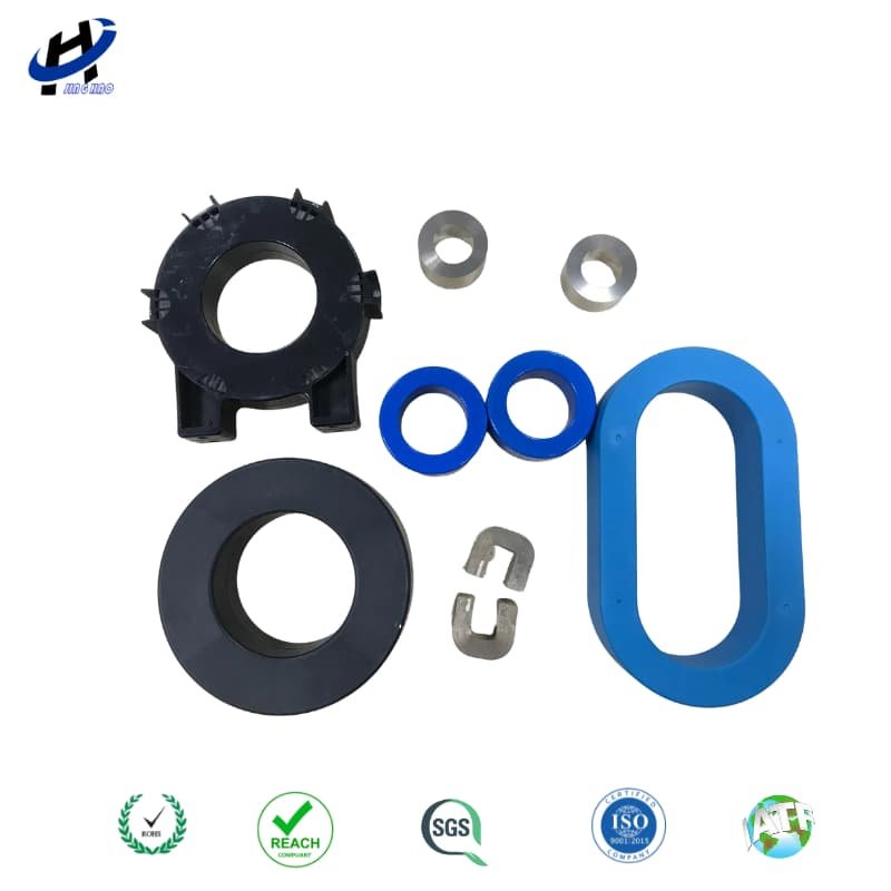
Cased cores for OEM HF stages — mechanical stack and varnish affect thermal and noise.
Gap, fringing, and thermal reality on HF stages
Every discrete gap bulges flux into the winding window. That fringe cuts copper, raises local eddy loss, and often puts the hottest spot on the turns hugging the cut faces—even when average current density looks fine. Treat “several gap lengths” as a keep-out intuition, document winding start relative to the gap mark, and verify with a thermal camera at your f_sw and ΔB, not only a cold AL meter. Depth on placement: air-gap fringing loss and winding placement.
Practical HF checklist:
Volt-seconds and ΔB budget at worst waveform (square / quasi-square / multilevel), not sine brochure loss alone.
Gap length tolerance and shim policy—AL drifts if clamp force or cut flatness changes lot to lot.
Cut-edge insulation after sawing/grinding so interlaminar shorts do not erase the nanocrystalline loss advantage—ceramic vs organic ribbon insulation questions.
Leakage and near-field around open paths; open geometry can move EMC plots even when efficiency looks good—open magnetic path EMI signatures.
Acoustic / magnetostriction if light-load patterns put energy in the audio band; impregnation and clamp stiffness matter on cut stacks.
Drawing freeze for second-source / dual-source cut C programs
Language discipline: say VAC/Finemet-class or comparable performance neighborhood when you mean incumbent correlation—not trademark equivalence. Translate into measurable windows. Buyer checklist depth for nanocrystalline dual source: what VAC/Finemet-class buyers should freeze before switching. Material-swap context when ferrite was in the old HF path: ferrite vs nanocrystalline—when each wins.
Assortment context — freeze role (transformer vs CT vs CMC) before OD alone.
Role: HF isolation transformer vs gapped energy-storage inductor vs hybrid—not “nanocrystalline C-core.”
Geometry stack: build, window, height, leg width, mean path, Ae/Aw, corner radius, mating face flatness.
Gap: nominal length, tolerance, shim material, clamp torque/force notes, gap mark for winding houses.
AL / loss: test frequency, excitation, bias if any, fixture notes; golden sample for meter correlation.
Finish: coating/case, cut-edge treatment, impregnation compatibility, what triggers a PCN.
Validation: thermal camera on gap-adjacent copper, efficiency / temperature rise at rated ΔB, EMI/near-field if leakage matters, acoustic if required.
Service-focused buyers in high-spec markets optimize requalification risk. A China second source that hits frozen gap and AL histograms is an engineering partner; a low quote that only matches outline dimensions is a future thermal or EMC reopen.
Application patterns (HF transformers and inverters)
PV / solar inverters: medium-frequency isolation or resonant stages where silicon steel loss explodes; nanocrystalline cut stacks shrink size when cooling is tight.
UPS and industrial HF PSUs: bobbin windings and serviceable cores; freeze gap so spare cores remain interchangeable years later.
Welding and induction heating supplies: high power density, harsh duty cycles; watch fringe heating on thick copper.
Medical / portable high-voltage pulse: mass and thermal margins matter; cut C geometry helps winding build for creepage.
Broader power-core assortment when the BOM mixes toroids and cut parts: nanocrystalline cores for power applications.
Clamp force, mating faces, and lot drift
Cut C performance is as much mechanical as magnetic. Mating-face flatness, burr height, and clamp force change the effective gap even when the shim stock is unchanged. A dual-source lot that “matches drawing gap” but arrives with different face finish will shift AL and fringe heating. Freeze face flatness / roughness notes, cleaning after cut, and torque or spring-clamp settings in the control plan. Ask for AL histograms from the proposed production clamp method—not only from a lab press used on first articles.
Ribbon insulation integrity after cutting belongs in the same review: conductive burrs short wraps and erase the nanocrystalline loss advantage under HF excitation. Pair gap metrology with edge-insulation checks before you blame the alloy grade.
FAQ
Q1: Can I replace a closed nanocrystalline toroid with a cut C-core of similar Ae?
Only after a full magnetic and EMI review. Cut geometry changes leakage, magnetizing inductance, and fringing. Treat it as a redesign gate, not a catalog swap.
Q2: Is a smaller gap always better?
No. Smaller gaps raise effective μ and AL but can push saturation under DC or magnetizing peaks; larger gaps linearize L yet intensify fringe heating. Freeze the gap that meets both L(I) and copper hotspot limits.
Q3: What does “VAC/Finemet-class cut C” mean on an RFQ to a China OEM?
A performance and correlation target against an incumbent sample—not a claim of trademark identity. Specify role, gap, AL/loss conditions, geometry, and finish/PCN rules.
Q4: Why did efficiency look fine but copper next to the cut faces burned?
Classic fringing eddy in the keep-out zone. Move the first turns, refine stranding, or revisit gap distribution before upsizing Ae as the first move.
Q5: Do automotive programs need PPAP on cut C transformer cores?
If the part is serial automotive, agree PPAP level and special characteristics (gap, AL, insulation) like any other magnetic core. Industrial programs still need a defined approval pack and change control.
For nanocrystalline cut C-core reviews on HF transformers or inverter stages (gap freeze, AL correlation, fringing keep-outs, second-source samples), contact julia@amorphousoem.com — www.amorphousoem.com.
Read More



 Room 701, Jizhou Tongde Street 45, Shijie Town, Dongguan City, Guangdong Province, China
 +86-180 2701 0075
 sales@amorphousoem.com


 IPv6 network supported |
Sitemap
|
XML
|
blogs
|
Privacy Policy