homepage
Leave A Message
If you are interested in our products and want to know more details,please leave a message here,we will reply you as soon as we can.
submit
banner
Home

Blog

Blog

  • How to Optimize High-Frequency Magnetics for Next-Gen Integrated OBC + DC/DC Converters under 800V EV Architecture
    How to Optimize High-Frequency Magnetics for Next-Gen Integrated OBC + DC/DC Converters under 800V EV Architecture
    May 24, 2026
    Discover how nanocrystalline cores solve core loss and thermal bottlenecks in 800V Integrated OBC + DC/DC designs utilizing SiC and CLLLC/DAB topologies. The electrification of the automotive industry is undergoing a massive architectural shift. As electric vehicles (EVs) transition from 400V to 800V platforms to unlock ultra-fast charging, the traditional decentralized power supply design is hitting its physical limits.   To achieve the critical industry goals of lightweight design and cost reduction, the market is rapidly moving toward Integrated OBC + DC/DC power conversion architectures. By sharing the DC-link bus, consolidating power semiconductor switches, and combining control boards, integrated systems can achieve up to a 30% reduction in volume and weight, alongside substantial BOM cost savings.   However, moving toward an integrated high-voltage, high-frequency domain introduces a severe secondary bottleneck: High-Frequency Magnetic Design. When switching frequencies shift into the hundreds of kilohertz (kHz) range via Wide Bandgap (WBG) semiconductors like Silicon Carbide (SiC) MOSFETs, conventional magnetic materials like manganese-zinc (MnZn) ferrites exhibit drastic core losses and thermal runaway.   To overcome this, next-generation integrated topologies—specifically CLLLC and Dual Active Bridge (DAB) resonant converters—require a fundamental material revolution: Nanocrystalline Cores.   1. The Architectural Evolution: Why Integrated OBC + DC/DC is Crucial for 800V EVs 
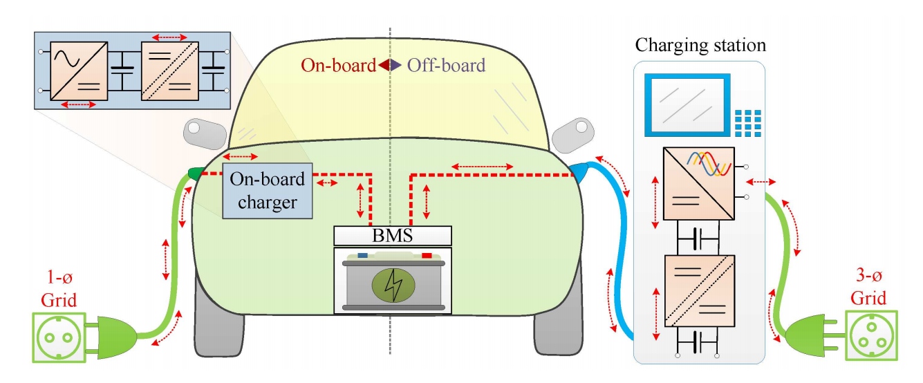
In traditional EV power architectures, the On-Board Charger (OBC) and the Low-Voltage DC/DC Converter (LDC) are treated as two isolated systems. Each possesses its own power factor correction (PFC) stage, isolated LLC/PSFB stages, independent microcontrollers (MCUs), cooling plates, and distinct housing enclosures. This decentralized approach leads to a massive component count, excessive high-voltage cabling, and a bulky footprint. The next-generation Power Domain Integration approach reorganizes this entirely. In a typical SiC-based Integrated OBC + DC/DC system, the hardware utilizes a highly integrated multi-port or shared-topology matrix: Shared High-Voltage DC-Link Bus: Eliminates one full stage of high-voltage capacitors and pre-charge circuits. Power Switch Multiplexing: In bidirectional topologies supporting Vehicle-to-Grid (V2G), the same primary-side SiC MOSFET bridges handle both incoming AC-to-DC grid charging and outgoing DC-to-AC power routing. Consolidated Thermal & EMI Systems: A single liquid-cooling plate handles the entire integration block, and the unified housing drastically simplifies Electromagnetic Interference (EMI) filtering layout. While this hardware compression achieves higher efficiency and volumetric power density, it forces the high-frequency magnetics—the main isolation transformers and resonant inductors—to handle significantly higher volt-second products and extreme high $dv/dt$ stresses within an ultra-compact space.   2. Topologies Driving the Integration: CLLLC vs. DAB Selecting the optimal circuit topology is the foundation of high-power-density EV power design. For integrated systems requiring bidirectional capability, two architectures dominate the 800V platform: The CLLLC Resonant Converter The CLLLC topology has emerged as the premier choice for bidirectional integrated OBCs. Featuring symmetric resonant networks on both the primary and secondary sides, it provides excellent soft-switching characteristics—achieving Zero Voltage Switching (ZVS) for the primary switches and Zero Current Switching (ZCS) for the secondary rectifiers across the entire wide battery operating voltage range. When paired with SiC MOSFETs operating at 100 kHz to 300 kHz, CLLLC structures drastically minimize switching losses. However, the performance of a CLLLC network is highly dependent on the stability of its resonant components. The leakage inductance of the transformer is often utilized as part of the resonant inductance, which requires incredibly tight control over magnetic flux leakage and core characteristics under variable thermal conditions. The Dual Active Bridge (DAB) Converter The DAB topology utilizes phase-shift control between two full bridges to regulate power flow. It offers excellent flexibility in managing wide input/output voltage variations, making it highly effective for the DC/DC converter stage routing power from the 800V traction battery down to the 14V/48V low-voltage auxiliary power module (APM). However, DAB converters can experience high circulating currents and loss of ZVS under light-load conditions, which induces sharp current spikes and elevates high-frequency AC copper losses (due to skin and proximity effects) and core losses in the main transformer.     3. The Magnetics Bottleneck: Why Ferrite Fails at High Frequency & High Voltage For decades, MnZn power ferrites have been the default choice for power transformers. But as EV power electronics push deeper into the 800V domain with fast-switching SiC devices, ferrites hit a definitive performance wall caused by three fundamental material limitations: Low Saturation Flux Density (Bsat): Power ferrites typically saturate between 0.4T and 0.5T at room temperature, dropping drastically to around 0.35T at 100°C. This low threshold forces engineers to use larger core cross-sectional areas (Ae), directly contradicting the requirement for high power density. Poor Thermal Conductivity: Ferrite is a ceramic material with low thermal conductivity (typically 3–5 W/m·K). Under high-frequency operation, the heat generated inside the core cannot escape efficiently, creating a severe localized temperature rise that quickly drives the material toward its Curie temperature, risking complete system failure. 
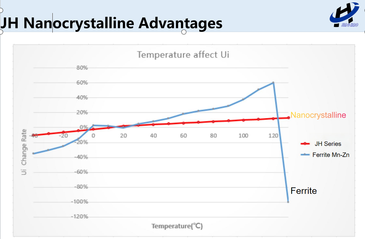
High Temperature Dependency of Losses: Ferrite core losses (Pv) are highly non-linear with respect to temperature. Minimum loss is usually tuned for 80°C or 100°C; if the system operates outside this window, losses spike rapidly, creating a dangerous positive thermal feedback loop.   
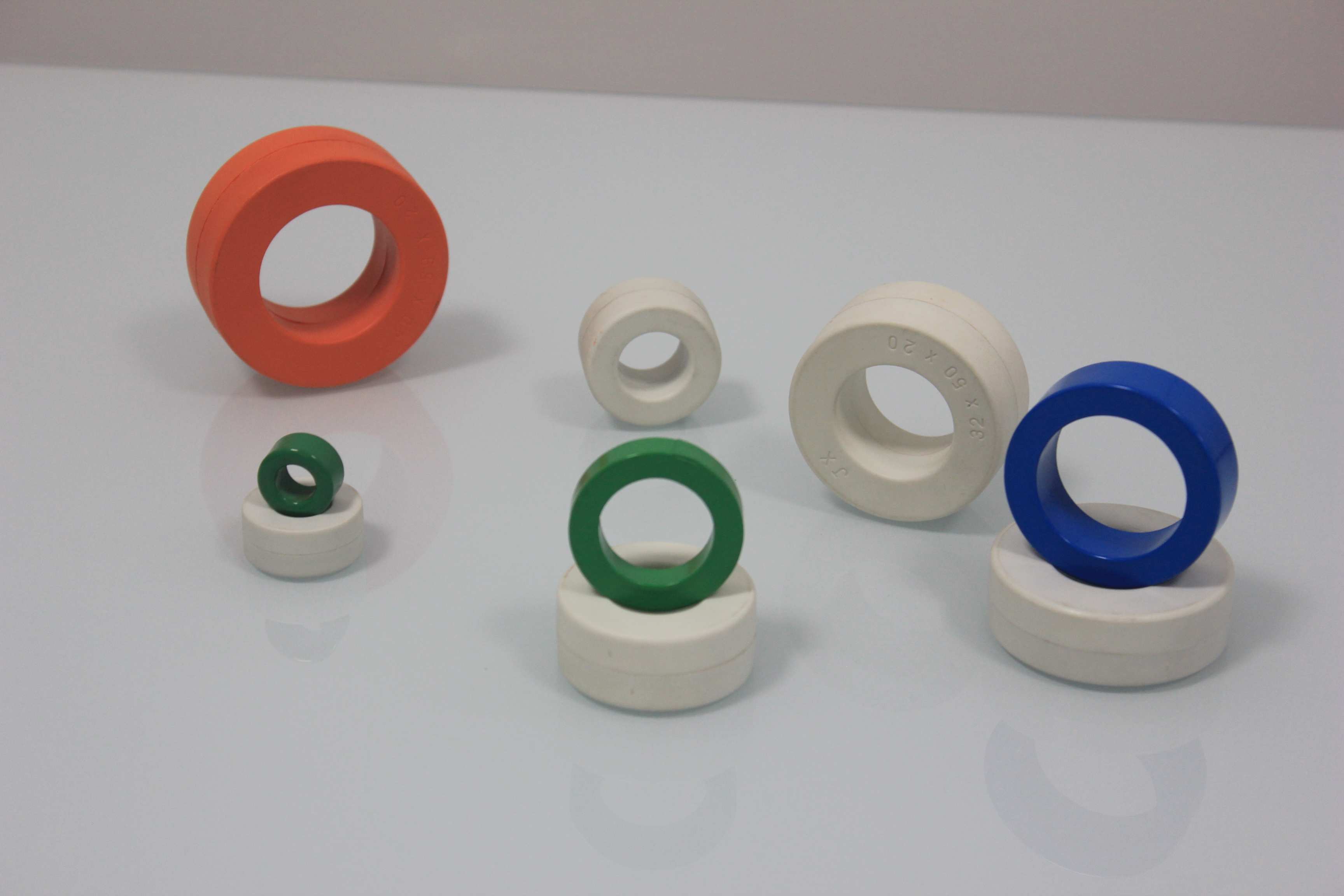
4. Nanocrystalline Cores: The Hidden Catalyst for High Power Density 
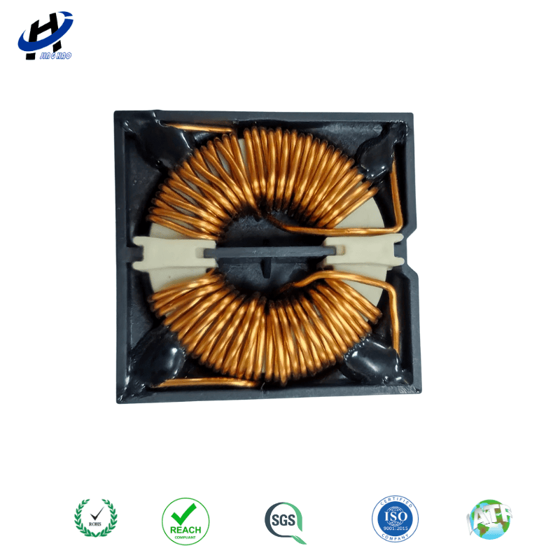
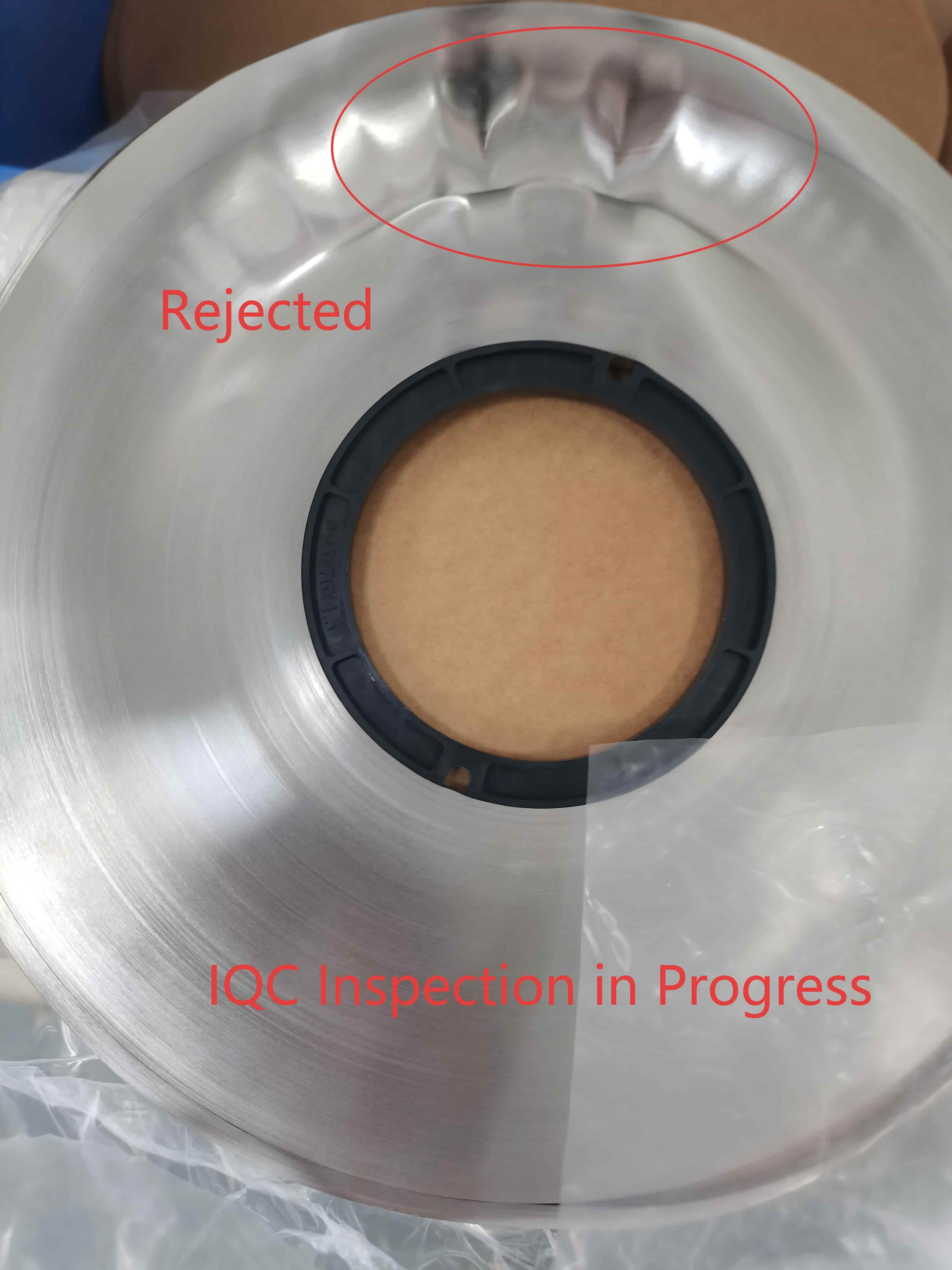
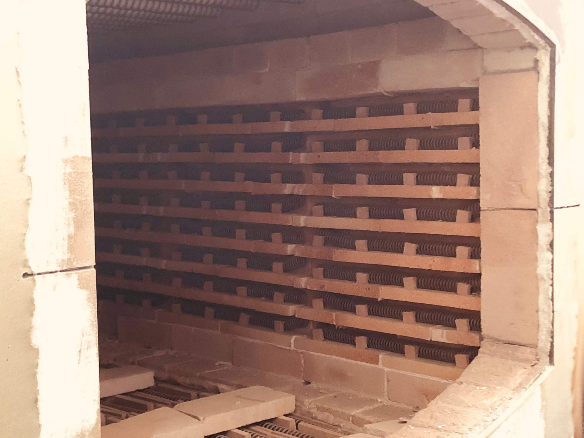
To break through the limitations of ferrite, next-generation integrated EV power electronics are pivoting to Fe-based Nanocrystalline Ribbons. Derived from rapid-solidification technology, nanocrystalline materials blend the high saturation induction of amorphous metals with the low losses of advanced ceramics. Magnetic Property MnZn Power Ferrite Fe-based Nanocrystalline  Saturation Flux Density (Bsat) ~0.45 T 1.2 T Initial Permeability (ui) 2,000 – 5,000 30,000 – 100,000 Core Loss (Pv) @ 100kHz, 0.2T ~100 kW/m³ ≤ 35 kW/m³ Curie Temperature (Tc) ~220°C > 560°C Operating Temperature Range -40°C to 125°C -50°C to 180°C   Shrinking the Footprint via 1.2T Saturation With a Bsat of 1.25T—nearly three times higher than ferrite—nanocrystalline cores allow design engineers to design with a much higher operational flux density (Delta B). According to the fundamental transformer design equation:   An increased Bm allows for a dramatic reduction in both the core cross-sectional area (Ae) and the number of winding turns (N). This creates a powerful compounding effect: a smaller core slashes total volume, while fewer turns significantly shorten the winding length, mitigating AC copper losses caused by high-frequency skin effects.   Extreme Thermal Stability Across Wide Load Profiles Unlike ferrites, whose loss profiles fluctuate violently across automotive temperature extremes (-40°C to 150°C), JH Amorphous' custom nanocrystalline chemistry delivers a nearly flat core-loss curve up to its operational limits. Boasting a Curie temperature exceeding 560°C, it completely eliminates the threat of high-frequency thermal runaway, ensuring ultra-reliable performance under harsh automotive environments.   
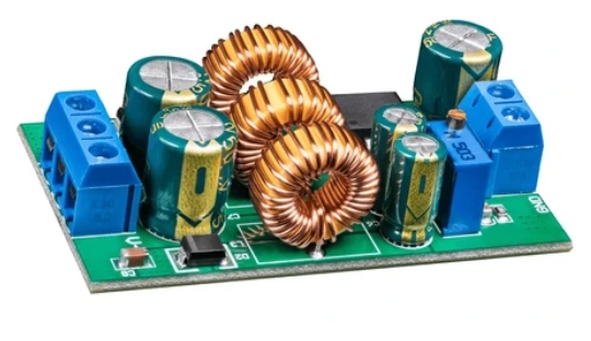
5. Advanced Component Design: Planar Transformers and Common Mode Integration Material selection is only half the battle. To fully unlock the performance of nanocrystalline materials in Integrated OBC + DC/DC systems, engineers must deploy advanced structural design methodologies.   Planar Transformers with Nanocrystalline Chokes For high-power density CLLLC and DAB converters, traditional wire-wound transformers are increasingly replaced by Planar Transformers. Utilizing multi-layer heavy-copper PCBs or lead-frame copper stampings as windings, planar designs achieve exceptionally low profile heights, outstanding thermal coupling to liquid-cooled cold plates, and highly repeatable leakage inductance profiles. Integrating a low-loss nanocrystalline magnetic shunt or gapped core within the planar structure allows for precise tuning of the leakage and magnetizing inductances needed for resonant tanks. This eliminates the need for an external, bulky discrete resonant inductor.   Multi-functional EMI Integration Integrated power conversion domains suffer from complex, overlapping noise spectrums. Fast SiC switching edges (dv/dt) induce severe Common Mode (CM) and Differential Mode (DM) electromagnetic noise.   By taking advantage of the ultra-high permeability (ui 80,000) of nanocrystalline alloys, engineers can design compact, multi-stage EMI filters. High permeability enables the required inductance to be achieved with fewer turns, reducing parasitic winding capacitance and pushing the self-resonant frequency (SRF) higher. This ensures excellent high-frequency attenuation across strict automotive noise limits.   Future-Proofing EV Power Designs with JH Amorphous The race toward 800V high-voltage platforms and Integrated OBC + DC/DC architectures demands more than just faster silicon or wider bandgap switches. It requires a fundamental shift in the passive components that manage the power. High-frequency magnetic design is the definitive bottleneck dictating the size, efficiency, and thermal boundaries of next-generation EV power electronics.   
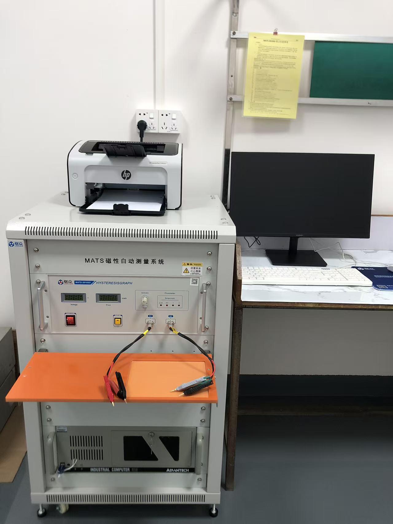
At JH Amorphous, we specialize in engineering high-performance Fe-based nanocrystalline cores, high-frequency transformers, and integrated magnetic assemblies tailored specifically for automotive power domains. Our advanced material processing guarantees ultra-low core losses under high $dv/dt$, high temperature stability, and optimized dimensional footprints to help you shrink your designs without compromising efficiency.   Contact Our Engineering Team   Ready to optimize your next 800V CLLLC or DAB converter project? Don't let magnetic core loss throttle your system's efficiency.   📩 Contact our application specialists today at julia@amorphousoem.com to receive custom magnetic core samples and comprehensive high-frequency loss characterization datasheets.
    Read More
  • Mastering EMI Suppression: A Comprehensive Guide to Common Mode Chokes
    Mastering EMI Suppression: A Comprehensive Guide to Common Mode Chokes
    May 12, 2026
    In modern power electronics and high-speed data transmission, noise is the enemy of performance. Whether you are designing a medical device or an EV charging system, managing Electromagnetic Interference (EMI) is critical for regulatory compliance and signal integrity. At the heart of this challenge is a vital component: the Common Mode Choke.   What is a Common Mode Choke? A common mode choke is an electromagnetic component used to filter out high-frequency noise shared by two or more power or signal lines. It provides high impedance to unwanted "common mode" noise while allowing the intended "differential mode" signals to pass through with minimal loss. How a Common Mode Choke Works   The device consists of two insulated copper coils wound around a single magnetic core. It operates based on the principle of magnetic field interaction: Common Mode Noise: Currents flow in the same direction on both lines. Their magnetic fields reinforce each other within the core, creating high resistance that "chokes" the noise.   Differential Signals: Desired currents flow in opposite directions. The magnetic fields cancel each other out, allowing the signal to flow freely without distortion.   Selecting the Right Core Material The magnetic core is the "brain" of the choke. The material you choose—whether it’s traditional ferrite or advanced nanocrystalline—directly dictates your filter’s frequency response and thermal limits.   1. MnZn Ferrite (Manganese-Zinc) Best for: Low-to-Mid Frequency Suppression (10kHz – 30MHz). MnZn ferrite is the industry standard for general EMI filtering. Key Benefit: High initial permeability (μi up to 15,000) provides massive impedance at low frequencies. Typical Use: AC/DC power supplies and household appliance filters.   2. Nanocrystalline (e.g., 1K107) Best for: High-Density & High-Temperature Applications. Nanocrystalline cores are the premium choice for modern hardware, offering high saturation induction (~1.25T). Key Benefit: Exceptional performance in a compact footprint and high stability up to 180°C. Typical Use: Electric Vehicle (EV) onboard chargers, solar inverters, and high-performance server supplies.   3. NiZn Ferrite (Nickel-Zinc) Best for: High-Frequency & Radiated EMI (>30MHz). Key Benefit: High electrical resistivity prevents eddy current losses at MHz and GHz frequencies. Typical Use: Data lines (USB-C, HDMI, CAN bus) and communication hardware.   Technical Material Comparison Material Type Permeability (μi) Saturation (Bs) Ideal Frequency Range Footprint MnZn Ferrite 5,000 – 15,000 ~0.5 T 10kHz - 30MHz Standard Nanocrystalline 20,000 – 190,000 ~1.2 T 10kHz - 50MHz+ Compact NiZn Ferrite 100 – 1,000 ~0.3 T 30MHz - 1GHz Standard   Frequently Asked Questions   What is the difference between a common mode choke and a normal inductor? A standard inductor filters both signal and noise (differential mode). A common mode choke specifically targets noise shared across lines while leaving the actual signal untouched.   When should I use Nanocrystalline instead of Ferrite? Choose nanocrystalline cores if your design has strict space constraints or operates in high-temperature environments. They offer superior energy density compared to traditional MnZn ferrites.   Reference: https://www.amorphousoem.com/blog/common-mode-choke-inductor-design-a-strategic-guide-to-high-performance-magnetics Need a Custom EMI Solution? Selecting the right material is essential for passing CISPR 32 or Class B limit lines. Contact our engineering team today to discuss custom core specifications for your next project.
    Read More
  • Are Your EMI Filters Ready for CISPR 32 Standards?
    Are Your EMI Filters Ready for CISPR 32 Standards?
    May 06, 2026
    Worried about EMI compliance? Discover how CISPR 32 impacts your designs and why switching to JH Amorphous Nanocrystalline cores is the ultimate key to passing Class B limits with higher efficiency and smaller footprints.   To ensure your EMI filters are ready for CISPR 32 standards, you must prioritize high-frequency impedance and thermal stability. The transition from CISPR 22 to CISPR 32 has tightened the limits for multimedia equipment, making traditional MnZn ferrite cores insufficient due to their lower permeability and saturation levels.   The most effective solution is integrating Nanocrystalline cores. These offer 10x the permeability of ferrites, allowing filters to achieve higher insertion loss in a 50% smaller volume while maintaining 99.5% efficiency.   What is CISPR 32 and Why Does It Matter? CISPR 32 is the international standard for the Electromagnetic Compatibility (EMC) of Multimedia Equipment (MME). It replaced the older CISPR 22 (ITE) and CISPR 13 (Audio/Video) standards to harmonize testing requirements for modern, integrated devices. For engineers, the primary challenge lies in the Class B conducted emission limits, which are particularly strict in the 150 kHz to 30 MHz range. If your EMI filter isn't optimized for these frequencies, your product simply won't hit the market.     The Bottleneck: Why Traditional Ferrites Fail CISPR 32 Tests Most engineers default to Manganese-Zinc (MnZn) ferrite cores for common mode chokes. However, as switching frequencies increase in SiC and GaN designs, ferrites encounter three major hurdles: Low Saturation (Bs): Ferrites saturate at ~0.4T, leading to catastrophic performance degradation under high current loads. Temperature Instability: Ferrite permeability drops significantly as temperatures rise toward 100°C, causing filters to fail during extended operation. Size Constraints: To meet CISPR 32 Class B, ferrite-based chokes often become too bulky for modern, compact enclosures.   The Nanocrystalline Advantage: Engineered for Compliance   At Dongguan JH Amorphous we specialize in Nanocrystalline cores that turn EMI compliance from a headache into a competitive advantage. Here is how our material outperforms traditional solutions:   1. Superior Permeability  Across Frequencies Our Nanocrystalline ribbons exhibit initial permeability ranging from 30,000 to over 150,000, whereas high-mu ferrites peak at 15,000. The Result: You get significantly higher impedance with fewer copper windings. This reduces parasitic capacitance and improves performance in the critical 10MHz+ range.   2. High Saturation Induction (1.25T) Nanocrystalline cores have a saturation induction (Bs) of 1.2T, triple that of ferrites. Design Impact: This allows the core to handle much higher DC bias currents without losing inductance, ensuring your EMI filter remains effective even at peak power loads.   3. The 50% Footprint Reduction By replacing a ferrite core with a Nanocrystalline core in high-power applications (like a 5kW inverter), engineers can reduce total filter weight by over 40% and volume by 50%.   Case Study: Passing CISPR 32 Class B in EV OBC Designs In Electric Vehicle On-Board Chargers (OBC), EMI filters must be ultra-compact. Using JH Amorphous Nanocrystalline Common Mode Cores, one client achieved: Insertion Loss: A +15dB improvement at 150kHz compared to NiZn/MnZn hybrids. Thermal Rise: Reduced by 22% due to the extremely low core losses  of our iron-based ribbons.   Checklist: Is Your Filter Ready for the Lab? Before your next EMC lab visit, ask these four critical questions: Does my choke saturate at max current? If so, you need the 1.2T headroom of Nanocrystalline. Is my impedance high enough at 150kHz? Nanocrystalline offers 10x the AL value of ferrite. Will the filter pass at 105°C? Nanocrystalline has a Curie temperature >560°C, compared to ferrite’s ~200°C. Is there enough space for cooling? Nanocrystalline’s efficiency significantly reduces heat dissipation needs.   Don't Let Magnetics Be Your Bottleneck   As power densities rise, the "old way" of using silicon steel or ferrite for EMI filters is becoming a liability. To meet CISPR 32 and stay ahead of the competition, Nanocrystalline is no longer an alternative—it is a requirement.   Ready to shrink your next design and pass EMC on the first try?   Contact Dongguan JH Amorphous today at julia@amphousoem.com to request our "Nanocrystalline vs. Ferrite" Loss Comparison Datasheet and sample kits.
    Read More
  • Why Do Traditional Ferrite Chokes Fail in Modern High-Frequency Converters?
    Why Do Traditional Ferrite Chokes Fail in Modern High-Frequency Converters?
    Apr 24, 2026
    As power densities increase and switching frequencies rise in GaN and SiC-based converters, traditional ferrite chokes often reach their physical limits. This post explores why Nanocrystalline and Amorphous CMC solutions from Dongguan JH Amorphous are becoming the new standard for high-performance power electronics.   The Limits of Ferrite in High-Density Design While cost-effective, ferrite cores suffer from relatively low Saturation Flux Density (Bs) and poor thermal stability (below 100 degree) In modern converters, this leads to: Thermal Runaway: Ferrites lose effectiveness as temperatures rise, a critical flaw in compact power supplies Size Constraints: To achieve the necessary inductance at high currents, ferrite chokes must become prohibitively large   The Amorphous Advantage Dongguan JH Amorphous specializes in Nanocrystalline cores that offer up to 10x the permeability of ferrite   This allows engineers to: 1. Reduce Volume: Shrink the EMI filter stage by up to 50% 2. Increase Efficiency: Lower copper losses due to fewer required windings 3. Broadband Suppression: Maintain high impedance across a wider frequency spectrum, addressing both conducted and radiated emissions   Are you looking to shrink your PCB footprint without compromising on EMI suppression? Let's discuss how our nanocrystalline technology can optimize your next-gen converter.
    Read More
  • Is Common Mode Noise Sabotaging Your Circuit Performance?
    Is Common Mode Noise Sabotaging Your Circuit Performance?
    Apr 23, 2026
      Abstract: Common Mode Chokes (CMCs) are essential passive components used to suppress high-frequency noise common to two or more data or power lines   While traditional ferrites are common, modern Amorphous and Nanocrystalline cores offer superior magnetic permeability and saturation levels, significantly enhancing EMI suppression in compact power electronic designs   The Role of a CMC in Modern Engineering In high-speed switching environments, electromagnetic interference (EMI) is an inevitable byproduct. A Common Mode Choke works by presenting high impedance to common-mode currents (noise) while allowing desired differential-mode currents (signals/power) to pass with minimal attenuation   Why Material Science Matters: Ferrite vs. Nanocrystalline For engineers in the industrial or EV sectors, the choice of core material is the difference between a passed or failed EMI test.   High Permeability: Nanocrystalline cores provide much higher impedance in a smaller footprint compared to standard ferrites   Saturation Flux Density: Amorphous materials handle higher peak currents without magnetic saturation, ensuring performance remains stable even under heavy loads   Is your current project facing stiff EMI challenges that standard off-the-shelf components can't solve? Contact our engineering team today for a free magnetic core selection consultation.  
    Read More
  • Is That Low Price Buying You a Product, or a Ticking Time Bomb?
    Is That Low Price Buying You a Product, or a Ticking Time Bomb?
    Apr 21, 2026
    "I remember a client back in 2023. They were searching for a reliable Nanocrystalline Core Manufacturer and found a supplier quoting 30% below the market average. They were thrilled, thinking they’d hit a gold mine of efficiency. Six months later, I got a frantic call. Their high-power inverters were failing in the field. The 'bargain' cores had lost 40% of their permeability in the field. It cost them their reputation with a Tier-1 automotive client. That’s when I told them: In this industry, if the price is that low, there are always Hidden Costs of Cheap Components."    After two decades in international trade—the last few specifically focused on the high-stakes world of magnetic components—I’ve seen this script play out a hundred times. We all want to optimize costs, but in technical manufacturing, there is a floor where "savings" transform into "systemic risk."   If you are currently Evaluating Magnetic Component Suppliers, here is the reality of what is often happening behind the scenes when a quote looks too good to be true:   1. Why CMC Cores Fail in the Field In the nanocrystalline and amorphous industry, quality is hidden in the heat treatment processing. To hit an impossible price point, some factories take shortcuts that compromise High-Frequency Core performance Stability: • The Single Annealing Shortcut: Proper magnetic stability requires precise, often multiple, magnetic field annealing steps. To save on electricity, some shops skip a cycle. The core looks fine during initial inspection, but its performance "falls off a cliff" after a year of application. • Recycled Scrap Material: Using lower-grade alloy ribbons slashes costs but introduces impurities. This is one of the leading Nanocrystalline Core Reliability Issues, leading to inconsistent flux density and higher core losses that eventually destroy your electronics.   2. The Financial "Shadow Games" Sometimes, a low price is a symptom of a supplier's desperate financial state. • Cash-Flow Traps: Some factories use low prices as bait to collect deposits quickly for high-interest lending. They delay payments to their own suppliers, creating a fragile chain that can collapse mid-order. • The Interest-Free Financing Scheme: They use your capital as a loan for six months and then claim they "cannot deliver." While you get your money back, your project deadlines have already gone up in flames.   3. The "One-Time" Business Model & Ethics Low-cost leaders often have no intention of a second deal. They may ship short quantities or ignore after-sales issues. Furthermore, when prices are extremely low, it’s crucial to vet the labor source. For companies in the West, Avoiding Procurement Fraud and unethical labor practices is not just about cost—it’s about protecting your brand from massive legal liabilities and customs seizures.   Summary for Procurement Managers When you see a price that defies logic, don't just look at the bottom line. Look at the annealing consistency and the factory's financial reputation. In the world of power electronics, the most expensive component is always the one that fails after it’s already been installed in your customer's system. Choose value, stability, and longevity over a temporary discount.
    Read More
  • Common Mode Choke Inductor Design: A Strategic Guide to High-Performance Magnetics
    Common Mode Choke Inductor Design: A Strategic Guide to High-Performance Magnetics
    Apr 13, 2026
    In modern power electronics, a "one-size-fits-all" common mode inductor simply doesn't exist. Every project brings a unique noise profile, mechanical constraint, and thermal limit. Designing an effective component requires balancing several moving parts: winding geometry, wire gauges, and core technology. To achieve optimal EMI suppression, you have to look at the inductor not just as a part, but as a complete system.   1. Structural Integration: Vertical vs. Horizontal Mounts The physical orientation of an inductor is rarely a matter of preference; it is a strategic response to the specific geometry of your PCB and enclosure. In high-power density designs, spatial management is as critical as electrical performance. • Vertical Mounts: These are the workhorses of high-density layouts. By utilizing the Z-axis, vertical inductors minimize the "real estate" occupied on the board. This is ideal for multi-component power stages where surface area is at a premium. However, the trade-off is height. You must ensure the component doesn't interfere with the chassis or create "dead zones" in the airflow path that could lead to localized hotspots. • Horizontal Mounts: When restricted by a low-profile chassis—common in slim-line server racks or compact EV modules—horizontal mounts are essential. While they occupy a larger footprint, they keep the center of gravity low and provide better mechanical stability under high-vibration conditions. The Rule: Lock in your orientation during the initial PCB floor-planning. Beyond physical fit, the core's orientation can influence magnetic coupling with nearby sensitive traces.   2. Encapsulation Strategy: Epoxy Coating vs. Plastic Casing How the bare core is wrapped is a strategic decision between "power density" and "mechanical robustness." • Epoxy Coating (The Slim Solution): This uses a micro-thin layer of insulation, offering minimal wall thickness. In space-constrained projects, a thinner coating allows for a larger bare core within the same footprint, maximizing impedance. It’s perfect for pushing the limits of volume, though it requires careful handling during assembly to avoid stress-induced performance shifts. • Plastic Casing/Header (The Rugged Solution): For high-voltage environments or heavy industrial machinery, this "armor" is often non-negotiable. The casing provides a robust safety barrier and superior vibration resistance. While the plastic takes up more room—meaning the internal core must be slightly smaller—the gain in insulation and structural integrity is vital for safety-certified systems.   3. Impedance Optimization and Frequency Response A common mode inductor’s effectiveness is a dynamic response to your circuit's specific noise profile. The goal is to hit peak impedance exactly where your switching noise is most aggressive, typically between  and . By leveraging nanocrystalline and amorphous materials, we can redefine the impedance-to-volume ratio. These materials offer significantly higher permeability across a broader spectrum than traditional ferrites. This means you can achieve superior noise suppression in a much smaller physical package. Always prioritize the impedance curve over a simple nominal inductance rating; a precision-engineered nanocrystalline core designed for your target frequency band will always outperform a generic high-inductance part.   4. Thermal Management and Wire Gauge Selection Heat is the ultimate enemy of reliability. Selecting the right wire gauge is a trade-off between DC Resistance (DCR), current-carrying capacity, and winding limits. • Passive Reliability: Most industrial designs rely on natural convection. We select wire diameters (typically 0.8mm to 2.0mm) to ensure the component remains "thermally invisible." This ensures that even under peak load, the inductor doesn't become a heat source that triggers thermal derating in nearby semiconductors. • Engineering Rule: Never sacrifice wire gauge just to add more turns unless the magnetic benefit significantly outweighs the thermal risk. A cool-running inductor with slightly lower inductance is almost always more reliable in the field.   5. The Art of Winding Geometry Winding is where theoretical design meets physical reality. The way the copper is laid down determines the actual high-frequency behavior of the part. • Managing Parasitics: The inner diameter (ID) of the core limits how many turns you can fit in a single layer. Moving to a second layer increases parasitic capacitance, which can "choke off" high-frequency performance. Nanocrystalline cores help here—their high permeability allows you to reach target inductance with fewer turns, keeping the winding to a clean, single layer. • Advanced Patterns: Winding geometry is a powerful tuning lever. For example, specific symmetrical patterns (like our "Style 2") consistently deliver higher impedance at high-frequency peaks. For heavy-duty industrial or EV power stages, we often utilize bifilar (parallel) winding to handle high current loads while maintaining thermal and magnetic equilibrium between the coils. By integrating these five pillars—structure, encapsulation, material frequency response, thermal safety, and winding precision—you move beyond off-the-shelf limitations and build a power system that is both compliant and exceptionally reliable.
    Read More
  • Why "100% Payment Before Shipping" Isn't a Safety Net Anymore
    Why "100% Payment Before Shipping" Isn't a Safety Net Anymore
    Apr 01, 2026
    For over 20 years in foreign trade, I lived by one rule: Get the full payment, ship the goods, and the deal is closed. It was a simple, "safe" mindset that I shared with many peers. But the 2026 revisions to the Maritime Law have completely flipped that logic.   The Harsh Reality of the New Law As of May 1, 2026, the law is clear: If a buyer abandons cargo at the destination port or fails to pick it up, the Shipper (You) is legally responsible for all resulting costs—storage fees, terminal charges, and disposal costs. Essentially, even if you’ve been paid in full, you are still the ultimate guarantor for that cargo until it clears the port. If the buyer disappears, the shipping line and the port won't chase a "ghost" buyer overseas; they will come after the person they can find: The Shipper.   How JH is Adjusting Our Strategy: Rethinking FOB: We used to think FOB meant "load it on the ship and forget it." Now, we realize FOB gives away control but keeps the tail-end risk. We are becoming much more involved in tracking the final delivery. Strict Client Vetting: We no longer just chase orders. We look for partners with real operational history and physical infrastructure. A buyer with high "sunk costs" is a safe buyer. In the magnetic core industry today, being a "top seller" isn't enough. You have to be a "top survivor." At JH, we choose to prioritize a robust, closed-loop supply chain over quick, risky wins.    
    Read More
  • Precision at the Core: Why Nanocrystalline Ribbon Uniformity Defines High-Frequency Reliability
    Precision at the Core: Why Nanocrystalline Ribbon Uniformity Defines High-Frequency Reliability
    Mar 23, 2026
    In the precision-driven world of magnetic component manufacturing, what you can’t see often matters most. A roll of nanocrystalline ribbon might look like a sleek, metallic masterpiece to the untrained eye, but for the engineering team at JH Amorphous, a single "wave" or surface irregularity is a red flag that demands immediate action. Quality in power electronics doesn't begin on the assembly line; it begins at the atomic level of the raw materials we source. When we encounter a batch of nanocrystalline ribbon with uneven surface tension or "wavy edges," we aren't just looking at an aesthetic flaw—we are looking at a performance compromise that could jeopardize an entire high-frequency project.   The Physics of Flatness: Why Microns Matter   Nanocrystalline alloys are the backbone of modern high-power density inductors and transformers. Typically measuring between 12 and 20 micrometers—thinner than a human hair—these ribbons are remarkably sensitive to physical stress. Surface uniformity is not a luxury; it is a technical requirement for three critical reasons: 1. Optimizing the Stacking Factor: To achieve maximum magnetic efficiency in a compact footprint, ribbon layers must be wound as tightly as possible. Any "waviness" creates microscopic air gaps between layers. This reduces the stacking factor, leading to unpredictable eddy current losses and thermal spikes that can shorten the lifespan of a component. 2. Eliminating the "Acoustic Hum": In applications like EV charging or medical imaging, silence is a performance metric. Uneven layers within a core can lead to magnetostriction-induced vibrations. By rejecting ribbons with surface deviations, we prevent the dreaded "transformer hum" before the core is even wound. 3. Preserving Magnetic Permeability: Nanocrystalline materials are stress-sensitive. Mechanical tension caused by winding an uneven ribbon directly degrades magnetic permeability. This results in inconsistent EMI filtering and lower overall efficiency in power conversion.   The JH Amorphous Standard: An Uncompromising IQC Process   At JH Amorphous, our Incoming Quality Control (IQC) is designed to be the ultimate filter. We utilize high-precision metrology and surface profilometers to audit every batch of ribbon. If a material exceeds our rigorous flatness tolerance (often within ±2μm), it is immediately flagged and rejected. This level of scrutiny might seem obsessive, but it is the only way to ensure the reliability of the components that power renewable energy grids and electric vehicle drivetrains. By maintaining a strict feedback loop with our material suppliers, we ensure that only "Grade A" nanocrystalline ribbons enter our cleanrooms. This proactive rejection of sub-par materials is what allows us to deliver inductors that run cooler, quieter, and longer than standard market alternatives.   Engineering Reliability from the Core Up   The difference between a component that merely "works" and one that "excels" lies in the details that most manufacturers overlook. While others might attempt to compensate for poor material flatness by adjusting winding tension, we believe in solving the problem at the source.   Selecting the right magnetic component starts with selecting a partner who understands the material science behind the product. If your current prototypes are struggling with thermal management or acoustic noise, the root cause may be hidden within the layers of the core material itself.   Our engineering team is ready to help you optimize your next design with materials that meet your customized standard . Whether you are developing the next generation of SiC/GaN inverters or high-speed rail power systems, we invite you to explore how our commitment to raw material integrity can elevate your project’s performance.   Discover our range of high-precision magnetic solutions or reach out to our technical team to discuss your specific material requirements.
    Read More
  • 24MW SST Design: Why Nanocrystalline Cores are the Heart of High-Frequency Power
    24MW SST Design: Why Nanocrystalline Cores are the Heart of High-Frequency Power
    Mar 17, 2026
    The shift from traditional grid transformers to 24MW Solid State Transformers (SST) is driven by the need for extreme power density and efficiency. Converting 20kV to 0.8kV at a switching frequency of 30kHz requires more than just high-end semiconductors; it requires a breakthrough in magnetic material science. At JH Amorphous, we don’t just supply parts. When a client approaches us with a high-power design, our first engineering question is: "What is the topology for this component?" This allows us to tailor our nanocrystalline solutions to the specific stresses of your circuit.   The Architecture: 20kV ISOP & 30kHz DAB Scaling a system to 24MW requires a modular approach. The Input-Series Output-Parallel (ISOP) topology is used to manage the 20kV input by cascading 33 individual modules. Inside each module, the Dual Active Bridge (DAB) converter operates at 30kHz. At this frequency, the magnetic core is the primary bottleneck for thermal management. This is where JH Amorphous’s material expertise becomes the critical factor in system reliability.   Why Nanocrystalline is Mandatory for 24MW SST In a 727kW module, ferrite cores often reach their saturation limits too quickly, leading to massive heat spikes. Our Nanocrystalline cores provide a superior alternative: High Saturation Flux Density (Bs:1.25T ): Our materials handle higher power in a smaller footprint, reducing the overall size of the SST. Minimal Core Loss: At 30kHz, JH Amorphous nanocrystalline ribbons exhibit significantly lower losses than traditional silicon steel or ferrite, enabling the system to exceed 98.5% efficiency. Thermal Stability: Engineered for the demanding environment of 24/7 grid operation.   Precision Control & Engineering Logic A successful SST design is a "symphony" of hardware and software. We optimize our magnetic components to support: ZVS (Zero Voltage Switching): Minimizing switching stress on SiC MOSFETs. Balanced Power Flow: Our cores are manufactured with tight tolerances to ensure consistent performance across all cascaded modules in the CHB string. Optimized Winding: We provide design consultation on Litz wire and copper foil integration to maximize the benefits of our high-permeability materials.   Powering the Future of Grid Technology At JH Amorphous, we understand that an engineer is the soul of the product. Our goal is to provide the "magnetic backbone" for your most ambitious power electronics projects. Ready to optimize your 30kHz transformer design? Contact Julia at JH Amorphous for technical datasheets and custom core benchmarking.
    Read More
  • How to Achieve "Zero Defects" in Vacuum Heat Treatment? A Deep Dive into Our Heating Control System
    How to Achieve "Zero Defects" in Vacuum Heat Treatment? A Deep Dive into Our Heating Control System
    Mar 14, 2026
    In the production of high-performance soft magnetic materials, such as nanocrystalline and amorphous cores, the annealing process is the ultimate bridge between raw material and peak magnetic performance. It determines permeability, saturation induction (Bs), and core loss.     Recently, during a factory tour, a client asked a sharp and vital question: "What happens to the product quality if a heating element in the vacuum furnace ages or a thermocouple fails during a cycle?" While this is a rare occurrence, at JH Amorphous, we treat "minimal probability" as a "must-solve challenge." Here is how we maintain a 100% quality rate through our Active Prevention and Passive Defense systems.   1. The Challenge: Why Temperature Precision is Non-Negotiable Nanocrystalline materials rely on a precise temperature profile to form their unique grain structure. A deviation of even 5°C can lead to uneven crystallization, compromising the consistency of the magnetic cores. Protecting the heating elements means protecting the product’s lifeline.   2. Active Prevention: Eliminating Risks Before They Occur Preventive Maintenance (PM): We don't wait for a burnout. We track the service life of every component and replace heating elements and thermocouples once they reach 80% of their theoretical lifespan. Regular TUS (Temperature Uniformity Survey): We periodically perform multi-point TUS using high-precision calibration tools to ensure the "Working Zone" inside the furnace maintains perfect thermal balance.   3. Passive Defense: Real-Time Monitoring & Redundancy PLC-Based Current Monitoring: Our furnaces are equipped with intelligent PLC systems that monitor the current in every heating segment. If a heating element shows a slight resistance drift or micro-crack, the system triggers an immediate "Current Imbalance" alert. Dual-Thermocouple Redundancy: We use a "Control + Monitoring" dual-thermocouple setup. If the primary sensor drifts by more than 2°C, the monitoring sensor identifies the discrepancy instantly and enters a safety mode.   4. The Quality Loop: Digital "Thermal Birth Certificates" Every batch of cores has a digital footprint. We log power consumption, vacuum levels, and temperature data every minute. If any electrical fluctuation occurs, that batch is automatically flagged for 100% magnetic performance re-testing. We aren't just selling magnetic cores; we are selling the reliability of a strictly controlled engineering process.   Whether you are designing for EV fast charging or smart grids, JH Amorphous is your stable partner.
    Read More
  • 2025 Year in Review: How JH Amorphous Reinvents Supply Chain Stability through Technical Upgrades
    2025 Year in Review: How JH Amorphous Reinvents Supply Chain Stability through Technical Upgrades
    Feb 14, 2026
    Introduction: In manufacturing, growth isn’t an abstract feeling—it’s a measurable reality. As a senior partner once asked: "Before we renew the contract, tell me what has improved in your company this year." At Dongguan JH Amorphous Co., Ltd. (JH Amorphous), we answered that question in 2025 through physical expansion, massive R&D investment, and global market validation.   1. Capacity Expansion: Scaling for Global Demand To meet the rising global demand for high-performance amorphous and nanocrystalline solutions, we officially expanded our manufacturing facility this year. This expansion isn't just about square footage; it’s about optimizing lean production workflows. This strategic move has significantly boosted our output capacity while ensuring "just-in-time" delivery stability.   2. Quality Moat: Investing in State-of-the-Art Testing Quality is the DNA of JH Amorphous. In 2025, we integrated industry-leading testing equipment to transition from manual checks to smart, data-driven analytics: Static MATS Machine: For high-precision magnetic property analysis, ensuring peak electromagnetic consistency. Temperature & Humidity Chamber: Rigorous environmental stress testing to guarantee long-term reliability in diverse climates. Auto Video Measure Machine: Micron-level dimensional inspection to eliminate human error and ensure mechanical precision.   3. Global Reach: Strategic Growth in the USA, Europe, and Australia Our commitment to international compliance and technical excellence has led to a major breakthrough in high-end markets. This year, we secured several Tier-1 clients across the USA, Europe, and Australia. While strict NDAs protect their identities, their trust validates our position as a premier global OEM/ODM provider.   Closing Thoughts: In an uncertain world, "Stability is the ultimate growth." We strengthen our capabilities so that your supply chain remains bulletproof. As we look toward 2026, JH Amorphous remains dedicated to being your most reliable link in the power electronics industry.
    Read More
1 2 3 4

leave a message

leave a message
If you are interested in our products and want to know more details,please leave a message here,we will reply you as soon as we can.
submit

home

products

WhatsApp

Contact