homepage
Leave A Message
If you are interested in our products and want to know more details,please leave a message here,we will reply you as soon as we can.
submit
banner
Home

nanocrystalline core

nanocrystalline core

  • Ferrite vs Nanocrystalline Cores for EMI and CMC: When Each Wins (and What to Freeze Before You Switch)
    Ferrite vs Nanocrystalline Cores for EMI and CMC: When Each Wins (and What to Freeze Before You Switch)
    Sep 30, 2026
    Ferrite and nanocrystalline are not drop-in twins If you design EMI filters or power magnetics for industrial, EV, or server-class PSUs, you have lived this choice: MnZn/NiZn ferrite on one side of the bench, iron-based nanocrystalline ribbon cores on the other. Brochure tables make the swap look obvious—higher Bs, higher μ, “better EMI.” On a real CMC or inductor drawing, the materials behave differently under bias, temperature soak, and AL fixture correlation. That gap is exactly where dual-source programs either land cleanly or reopen EMC after SOP. This article is written for high-spec buyers in JP, CA, US, FR, UK, IT, RU, and similar markets who already ran VAC Vitroperm-class or Hitachi Metals Finemet-class nanocrystalline programs and now need a China OEM as engineering second source—not a cheap catalog substitute. Dongguan JH Amorphous Co., Ltd. (www.amorphousoem.com) supplies OEM/ODM amorphous and nanocrystalline cores under ISO9001:2015 and IATF 16949. We help freeze grade intent, AL/Z windows, and change control so a second source supports your filter, not quietly rewrites it. What each material actually is (in magnetics terms) Ferrite is a sintered ceramic (iron oxide plus Mn/Zn or Ni/Zn oxides). High resistivity keeps eddy currents low; shapes are moldable (toroids, E/U cores, beads). MnZn grades are the usual workhorse for power and mid-band EMI; NiZn typically pushes higher frequency at the cost of lower μ. Saturation flux density for common MnZn CMC grades sits roughly in the ~0.3–0.5 T neighborhood. Curie temperatures are relatively low, so permeability and loss can move hard as the hotspot approaches ~100–120°C—see high-temperature magnetics when ferrite derates. Nanocrystalline starts as rapidly solidified Fe-Si-B-Nb-Cu (and related) amorphous ribbon, then anneals into ~10–20 nm grains. Finished cores are usually cased or coated toroids / cut cores. Typical iron-based grades used in CMCs offer Bs around ~1.2–1.25 T class, very high initial permeability (often discussed as tens of thousands to >80,000 depending on grade and test conditions), low magnetostriction, and alloy Curie near ~570°C. The finished assembly still lives inside copper enamel, case polymer, and varnish limits—often discussed about -40°C to +140°C for the wound part. High-μ CMC grades and lower-μ energy-storage / inductor-oriented finishes are different anneal philosophies; mixing them by OD alone is the classic μ trap. Coated ribbon cores — finish and insulation belong on the drawing with grade, not as an afterthought. Comparison table: EMI / CMC / power magnetics tradeoffs Numbers below are order-of-magnitude engineering neighborhoods for discussion—always lock AL or impedance at your frequency, excitation, and fixture. Do not treat trademark alloy families as interchangeable by name; when buyers say “VAC/Finemet-class,” translate into measurable windows on the drawing. Property / decision Ferrite (typical MnZn CMC / power) Iron-based nanocrystalline (CMC-class) Composition Ceramic oxide (MnZn / NiZn) Metallic ribbon alloy (Fe-Si-B-Nb-Cu class), annealed Bs (order) ~0.3–0.5 T ~1.2–1.25 T class Initial μ (order) ~1,500–15,000 (grade-dependent) Very high (often >> ferrite; grade & test condition driven) Useful EMI band (CMC practice) Strong mid–high MHz; NiZn for HF beads Strong from tens of kHz into several MHz; broadband CM impedance Thermal / Curie story Softens near ~100–120°C hotspot class Alloy Curie ~570°C; assembly limited by Cu/case (~-40 to +140°C class) Core loss / size Higher loss → larger stack for same EMI/thermal Lower loss, fewer turns, smaller volume for high-current CM Mechanics Brittle ceramic; moldable shapes Thin ribbon; needs case/varnish; winding stress matters Relative piece cost Usually lower Higher unit price; often lower system EMI/thermal cost When it wins Modest current, cool ambient, HF-only noise, cost-sensitive SMPS High CM current, low-frequency EMI, hot EMI soaks, size-constrained OBC/inverter For choke sizing practice—AL, OD/ID/HT, casing, and impedance bands—use the common mode choke selection guide. Product-family context for wound CMC cores: nanocrystalline common mode choke cores. Cased nanocrystalline CMC cores — high Bs and high-μ grades for low-frequency / high-current common-mode stages. When ferrite still wins Nanocrystalline is not a blanket upgrade. Ferrite remains the right call when: Noise is high-frequency and current is modest. NiZn beads and small MnZn CMCs often cover MHz-range conducted/radiated issues without paying for high Bs. Hotspot stays cool. If thermal mapping shows the core well below the ferrite soft region, μ collapse is not your limiter—copper or layout may be. Shape and gap freedom matter more than Bs. Complex E/U geometries, adjustable gaps, and multi-gap stacks are mature in ferrite tooling. Cascade filters already mix materials. Many industrial EMI stages use ferrite on the HF end and nanocrystalline on the low-frequency / high-current CM stage. Replacing both with one alloy because of a brochure is rarely optimal. Cost-only consumer SMPS with loose EMI margin where requalification risk is low and ambient is gentle. Related material discussion: how core materials define CMC performance. When nanocrystalline (VAC / Finemet-class performance neighborhood) wins Use nanocrystalline when the failure mode is saturation under CM surge / bias, insufficient impedance below a few hundred kHz, or EMI that collapses after a hot soak on ferrite. Typical contexts: EV onboard chargers and DC-DC front-ends, high-power industrial inverters, compact UPS/server PSUs, and multi-frequency noise where fewer turns and higher Bs shrink the filter. Bs headroom (~1.25 T class vs ~0.4 T ferrite) lets you hold inductance under peak current that would drive ferrite soft. Language discipline for RFQs: say VAC/Finemet-class or comparable grade when you mean a performance neighborhood (high-μ CM vs inductor finish, Bs/thermal story, AL window). Do not claim trademark equivalence or identical chemistry unless your lab and legal teams have that evidence. Most dual-source programs prove fit-for-function on the wound CMC or inductor against an incumbent sample. Checklist depth: second-sourcing nanocrystalline cores—what VAC/Finemet-class buyers should freeze. Saturation, permeability, and thermal—what actually breaks EMI Saturation. Ferrite’s lower Bs means CM surge or DC bias collapses μ earlier; the choke looks fine at light load and fails under load dump or motor start. Nanocrystalline delays that collapse, but an open magnetic path, poor lead dress, or wrong AL still fails EMC. Geometry mistakes are not fixed by alloy brand heritage. Permeability. Very high μ gives high CM impedance with fewer turns (lower copper loss), yet it is also easier to mis-apply: a high-μ CMC core pressed into gapped energy-storage duty, or an inductor-oriented grade sold into a CM filter, both look “nanocrystalline” on the PO and wrong on the spectrum analyzer. Freeze magnetic role on the drawing. Thermal. Ferrite derating near ~100–120°C is a magnetic story. Nanocrystalline’s high Curie is an alloy story; the wound choke still dies from enamel, case continuous-use temperature, or copper resistivity rise. Map hotspots, then decide whether μ/Bs collapse or assembly limits dominate. Insulation and casing choices belong in the same review as grade—ceramic vs organic ribbon insulation. Gapped inductor builds need winding keep-outs from fringe fields—air-gap fringing and winding placement. Second-source drawing freeze notes (before you switch materials or suppliers) Whether you move ferrite → nanocrystalline or dual-source a Finemet-/Vitroperm-class incumbent to a China OEM, freeze these items before samples leave the plant: Role: CMC (closed-path high-μ) vs inductor / PFC (gapped or lower-μ) vs CT—not “nanocrystalline toroid.” AL or Z window at stated frequency, excitation, and fixture notes; keep a golden sample for meter correlation. Geometry stack: OD/ID/HT, case type, gap mark, lead egress for the winding house. Insulation / coating / varnish system and what triggers a PCN. Thermal & EMI validation: wound-sample delta vs incumbent (conducted/near-field as applicable) after soak. QMS path: IATF scope when automotive, agreed PPAP level, change control—see IATF 16949 and PPAP for magnetic core suppliers. OEM core assortment — freeze role (CMC vs CT vs inductor) before OD alone drives the PO. Service-over-price buyers optimize requalification risk and field EMI, not piece price alone. A China second source that hits frozen AL histograms and PCN discipline is an engineering partner; a low quote that only matches OD is a future EMC reopen. Practical decision path List noise band, I_rms / I_peak CM, ambient and hotspot budget. If ferrite EMI fails after thermal soak or under surge—shortlist nanocrystalline CMC-class cores. If noise is HF-only and current/temperature are gentle—keep ferrite or cascade both. Size AL/Z and copper; verify on the wound part, not brochure μ. For dual source after VAC/Finemet-class history: freeze the drawing list above, then correlate samples. FAQ Q1: Can I drop a nanocrystalline toroid into a ferrite CMC footprint one-for-one? Sometimes on OD/ID/HT, rarely on electrical behavior without revalidating turns, AL, leakage, and EMI. Treat it as a design review, not a catalog swap. Q2: Is nanocrystalline always better for EMI? No. It usually wins on high-current / low-frequency CM and thermal stability of the magnetic function. Ferrite can still win at HF with modest current, or in cascade stages. Q3: What does “VAC/Finemet-class” mean in an RFQ to a China OEM? A performance neighborhood and incumbent correlation target—not a claim of trademark identity. Specify role, AL/Z conditions, geometry, insulation, and EMI/thermal delta expectations. Q4: Why did my ferrite CMC pass cold and fail after soak? μ and loss often move as ferrite approaches its soft thermal region (~100–120°C class). Re-map hotspot; consider nanocrystalline if magnetic derating is the limiter. Q5: What should purchasing and engineering freeze together? Grade intent (CMC vs inductor), AL/Z window with test notes, mechanical stack, insulation/PCN rules, and validation against the incumbent. Price alone should not reopen EMC. For ferrite-to-nanocrystalline reviews or VAC/Finemet-class second-source drawing checks (AL correlation, sample planning, CMC grade selection), contact julia@amorphousoem.com — www.amorphousoem.com.
    Read More

  • Second-Sourcing Nanocrystalline Cores: What VAC / Finemet-Class Buyers Should Freeze Before Switching
    Second-Sourcing Nanocrystalline Cores: What VAC / Finemet-Class Buyers Should Freeze Before Switching
    Sep 29, 2026
    Why OEMs second-source nanocrystalline cores now Many power and EMI designs in Japan, North America, and Europe were frozen around well-known nanocrystalline brands—often discussed in the same breath as VAC Vitroperm-class or Hitachi Metals Finemet-class materials. Those programs still need high-μ CMCs, stable AL, and predictable EMI. What changed is supply strategy: dual source, shorter sample loops, and China OEM capacity that can hit engineering windows when drawings are written tightly. Second-sourcing is not “buy the cheapest toroid labeled nanocrystalline.” It is locking the magnetic grade intent, test conditions, and change control so a China manufacturer can support—not quietly rewrite—your filter or inductor. Dongguan JH Amorphous Co., Ltd. (www.amorphousoem.com) supplies OEM/ODM amorphous and nanocrystalline cores under ISO9001:2015 and IATF 16949. This article is a buyer/engineer checklist for second source and dual source programs aimed at service-sensitive markets (US, Canada, UK, France, Italy, Japan, and similar), not a price war playbook. Buyer priority What to freeze What fails if you skip it Role: CMC vs inductor Grade family (high-μ CM vs energy-storage / lower-μ) μ trap, wrong EMI or saturation behavior Geometry OD/ID/HT, case, gap mark, lead egress Winding house scrap, harness EMI AL / Z window Test frequency, excitation, fixture notes Lots that “pass OD” fail on the bench Quality system IATF scope, PPAP level, PCN rules Quiet process drift after SOP Validation EMI/thermal delta vs incumbent sample Field returns after dual-source swap Plastic-cased toroids: second-source reviews start with magnetic role and AL windows. VAC / Finemet-class language—without false equivalence Purchasing often says “VAC alternative” or “Finemet equivalent.” Engineering should translate that into measurable targets: permeability class for CM vs DM duty, Bs and thermal story vs ferrite, core loss at your kHz, dimensional stack for the winding house, and insulation/coating system. Trademarked alloy families are not interchangeable by name. Treat them as performance neighborhoods you reverse-engineer into a drawing. Claim “same brand chemistry” only when your lab and legal teams have that evidence—most second-source programs instead prove fit-for-function on the finished CMC or inductor. Useful framing for RFQs to China OEMs: Application: CMC / PFC inductor / cut C-core / CT—not “nanocrystalline toroid.” Incumbent sample available for AL correlation and EMI delta (preferred). Target AL or impedance band at stated conditions; reject “typical μ” as the only spec. Annual volume, sample lead time, and whether PPAP (or customer PPAP-like pack) is required. Contact path to applications engineering, not only sales. Related reading on the grade mistake that kills dual-source programs: the μ trap on nanocrystalline datasheets. For automotive paperwork depth, see IATF 16949 and PPAP for core suppliers. What to put on the drawing before you dual-source Magnetic role. High-μ closed-path grades for CM impedance are not the same anneal philosophy as gapped or lower-μ energy-storage cores. If the incumbent was a CMC, do not accept an “inductor-looking” nanocrystalline with a gap unless EMI and thermal are revalidated. Cut cores and fringing need their own keep-outs—see air-gap fringing and winding placement. AL / impedance. State frequency, waveform notes, and fixture correlation. Keep a golden sample when the second source uses a different AL meter. Lot histograms beat single-point brochure numbers. Mechanicals and insulation. Case resin, varnish, ceramic vs organic ribbon insulation, and edge condition affect hi-pot, thermal, and winding damage. Ask what changes trigger a PCN. Background: ceramic vs organic insulation questions for OEM buyers. Thermal and EMI context. Ferrite may be discussed as soft near ~100–120°C; nanocrystalline alloy Curie is far higher (~570°C class), but finished assemblies still live inside copper and plastic limits (often discussed about -40°C to +140°C). Open magnetic paths and poor lead dress still fail EMC regardless of brand heritage—open-path EMI signatures and high-temperature magnetics. Coated toroids across sizes: freeze the coating/insulation system when dual-sourcing an incumbent. Validation that service-focused buyers actually run Price-insensitive customers still hate requalification surprises. A practical second-source gate: Dimensional FAIR against the frozen drawing. AL / Z distribution on N pieces from the proposed production route. Wound sample: copper rise, acoustics if relevant, and near-field or conducted EMI delta vs incumbent. Thermal soak if ferrite was in the old path or ambient is hot. Paper: certificate scope page, control-plan outline, material declarations, agreed PPAP level for automotive. Field context from programs that already exercised nanocrystalline CMCs under real EMI/thermal pressure: German 800 V EMI case, Italian EV charger thermal/EMI case. Product examples to anchor RFQs: nanocrystalline cores for common mode chokes, cut C-cores for power magnetics, CMC selection guide. Market cue What they usually optimize Supplier behavior that fits US / CA / UK Drawing discipline, English FAE, dual source risk Clear AL windows, sample speed, PCN in writing DE / FR / IT EMC + automotive/industrial QMS IATF-aware packs, EMI delta data JP Consistency, packaging, communication quality Tight tolerances, lot codes, responsive FAE Other high-spec OEMs Second source without redesign Incumbent correlation, not catalog guesswork Oval / racetrack cores: lock window and build dimensions on the drawing, not just OD. Case and base options: resin, lead egress, and mounting belong in the change-control plan. Wound CMC assembly: prove fit-for-function with EMI and thermal delta against the incumbent. FAQ Q1: Can a China OEM replace a VAC- or Finemet-class core one-for-one? Sometimes on geometry and AL windows, never by trademark name alone. Prove fit-for-function on the wound part and freeze grade intent on the drawing. Q2: What is the fastest way to fail a second-source trial? Ordering by OD and “nanocrystalline” without CMC vs inductor grade, AL test conditions, or EMI delta against the incumbent. Q3: Do we need full PPAP for every dual-source core? Automotive serial parts usually yes at the agreed level; industrial programs still need a defined approval pack and PCN rules. Details: IATF/PPAP guide. Q4: Should we dual-source different anneal philosophies? Not without full requalification. Two routes that only share OD are two different parts electrically. Q5: Who should own the RFQ—purchasing or engineering? Both. Purchasing owns commercial dual-source risk; engineering owns magnetic role, AL, and EMI. JH Amorphous expects joint reviews so piece price does not reopen EMC. For second-source or dual-source nanocrystalline / amorphous core reviews (drawing check, AL correlation, sample planning), contact julia@amorphousoem.com — www.amorphousoem.com.
    Read More
  • How Coating Affects Nanocrystalline Cores: Performance, Process, and Innovation | JH Amorphous
    How Coating Affects Nanocrystalline Cores: Performance, Process, and Innovation | JH Amorphous
    Oct 22, 2025
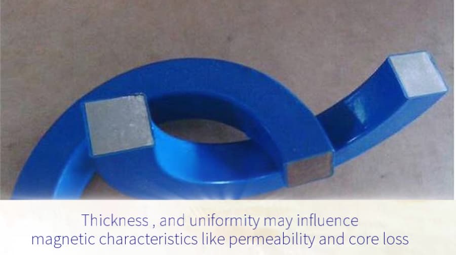
    Learn how coating impacts nanocrystalline cores in terms of performance, magnetic properties, and production efficiency. Discover how JH Amorphous optimizes coating technology for stability, cost-effectiveness, and innovation.   Nanocrystalline cores are essential in modern magnetic materials used in transformers, inductors, and other electronic devices. While their internal structure defines the magnetic properties, the coating applied to the core also plays a major role in determining performance, durability, and cost efficiency.   For high-quality nanocrystalline cores, coating materials must meet strict performance requirements. During the coating process, the layer should not create excessive stress that can damage the core. Once cured, the coating needs to offer high hardness, dimensional stability, good adhesion, insulation, and solvent resistance. These characteristics help maintain magnetic stability and ensure reliable performance throughout the product’s lifetime.   Because nanocrystalline cores often have ring-shaped structures, flexibility, and no chamfer, the coating process must be carefully selected. A dual-sided spraying method is often used to achieve uniform coverage across all magnetic surfaces, including edges and corners. This approach minimizes coating stress and prevents uneven thickness, which can lead to magnetic distortion or cracking. Proper control of parameters such as spray angle, coating viscosity, and curing temperature ensures both functional and aesthetic quality.   The coating also directly influences magnetic performance. Stress, coating thickness, and uniformity can all affect properties like magnetic permeability, core loss, and coercivity. Even small inconsistencies may cause changes in these parameters, reducing performance and efficiency. By optimizing coating parameters, manufacturers can minimize these effects and maintain stable magnetic characteristics. At JH Amorphous, advanced process control is used to ensure that every coating application supports the core’s intended performance.   Beyond performance, the coating process affects production efficiency and cost. Factors such as equipment speed, coating utilization, and material waste determine overall productivity. By optimizing these elements, JH Amorphous achieves higher throughput, lower waste, and more consistent quality. The result is a more efficient and sustainable manufacturing process that benefits both production and performance goals.   Continuous innovation is key to staying ahead in nanocrystalline technology. JH Amorphous continues to explore new coating materials and automated processes that enhance insulation, adhesion, and durability while maintaining environmental responsibility and cost-effectiveness. Through these efforts, the company delivers reliable and energy-efficient nanocrystalline cores that meet the evolving demands of global industries.     Coating may appear to be a small step in manufacturing, but it has a major impact on how nanocrystalline cores perform in real-world applications. Every layer counts — and with the right materials, processes, and innovation, coating becomes a crucial factor in achieving superior magnetic performance and long-term stability.   Video link:  https://www.amorphousoem.com/video/the-impact-of-coating-on-nanocrystalline-cores About Dongguan JH Amorphous Co., Ltd. Dongguan JH Amorphous Co., Ltd. is a professional manufacturer specializing in amorphous and nanocrystalline magnetic cores and parts.We serve industries including power electronics, renewable energy, automotive electrification, and industrial automation, offering both standard and custom magnet solutions. Contact Information:📧 julia@amorphousoem.com🌐 www.amorphousoem.com   Author:Julia YimInternational Marketing ManagerDongguan JH Amorphous Co., Ltd.
    Read More
  • 191125 Size Nanocrystalline Magnetic Core for Automotive Inductor: Reliable Speed-Limiting Solution for EV and Car Electronics
    191125 Size Nanocrystalline Magnetic Core for Automotive Inductor: Reliable Speed-Limiting Solution for EV and Car Electronics
    Aug 26, 2025
    With the rapid growth of electric vehicles (EVs) and intelligent automotive systems, the demand for high-performance inductors has never been greater. Automotive electronics require components that deliver stable inductance, low power loss, and long-term reliability under harsh conditions. Among them, the 191125 size nanocrystalline magnetic core  inductor stands out as an excellent solution for speed-limiting inductor applications, onboard chargers, and automotive power management modules. This article provides a comprehensive overview of the product’s features, advantages, and application value in the evolving automotive industry. 1. What is the 191125 Size Nanocrystalline Core for Inductor? The 191125 nanocrystalline magnetic core is designed bear core outside dia. 19mm, inner dia. 11mm, height 25mm, Fe-based nanocrystalline 1K107B material. At a working frequency of 100KHz, it delivers a stable inductance value ranging between 52μH and 73μH. The product is optimized for automotive-grade environments, ensuring consistent performance even under extreme conditions such as high temperature, vibration, and electromagnetic interference. In automotive applications, speed-limiting inductors are critical to electromagnetic compatibility (EMC). They help suppress high-frequency noise and stabilize current flow, preventing malfunctions in sensitive electronic systems. By adopting nanocrystalline material, the 191125 inductor combines compact size with superior magnetic performance. 2. Advantages of Nanocrystalline Magnetic Core Compared with traditional ferrite cores, nanocrystalline cores offer significant benefits: High Permeability: Enables higher inductance values with fewer turns, saving space and reducing cost. Low Core Loss: Ensures excellent efficiency at high frequencies, making it suitable for EV power electronics. Temperature Stability: Maintains consistent inductance over wide operating ranges (-40°C to +150°C). Superior EMI Suppression: Effectively reduces noise, ensuring system-level stability in automotive circuits. These properties make nanocrystalline cores ideal for EV power conversion systems, DC/DC converters, onboard chargers, and noise suppression circuits. 3. Key Specifications of the 191125 Nanocrystalline core Size(mm): bear core: OD:19  ID:11  HT: 25 , Coated finished core:  OD:19.5  ID:10.5  HT: 25.5 Structure: wound nanocrystalline core Frequency Range: Optimized for 100KHz operation Single Inductance Value: 52μH – 73μH Application Focus: Automotive speed-limiting inductors, EV power management modules, onboard charging units Such specifications prove the product’s suitability for automotive-grade performance, ensuring reliability in demanding EV systems. 4. Automotive Application Scenarios a. Electric Vehicles (EVs) The 191125 nanocrystalline inductor plays a critical role in EV motor control systems and battery management modules, where stable inductance ensures smooth current handling and improved energy efficiency. b. Automotive Power Management Modules In DC/DC converters and inverters, stable inductance minimizes ripple current, reduces heat generation, and improves overall system reliability. c. Speed-Limiting Inductor Applications As part of EMC compliance, speed-limiting inductors filter noise spikes and protect circuits against interference, ensuring safe vehicle operation. d. Onboard Chargers & Charging Stations In OBCs and fast-charging systems, inductors with low loss and high stability improve charging efficiency and extend battery life. 5. Why Choose the 191125 Nanocrystalline core for Automotive Inductor? Automotive-Grade Reliability: Designed for high vibration, temperature, and humidity environments. Stable Inductance Range: 52–73μH at 100KHz ensures predictable and efficient performance. Long Lifespan: Nanocrystalline core materials reduce wear and degradation over time. Energy Efficiency: Lower losses help optimize EV range and reduce heat dissipation. Broad Applicability: Suitable for EVs, hybrid vehicles, onboard chargers, and smart automotive systems. 6. Market Trend and Industry Outlook The global automotive inductor market is expanding rapidly, driven by the adoption of EVs, hybrid cars, and intelligent vehicle platforms. According to industry forecasts, demand for automotive-grade inductors will grow at double-digit rates over the next five years. Nanocrystalline inductors are expected to dominate future applications due to their superior performance in high-frequency, high-power environments. The 191125 nanocrystalline core for inductor is well positioned as a reliable choice for next-generation EV power electronics. The 191125 size nanocrystalline magnetic core for automotive inductor core combines stable inductance (52–73μH), low core loss, EMI suppression, and automotive-grade durability, making it the ideal solution for speed-limiting applications and other car electronics. For more insights, contact JH Amorphous engineer team via sales@amorhpousoem.com.    As the world moves toward greener, smarter, and more energy-efficient transportation, choosing high-performance inductors is critical. The 191125 inductor not only enhances vehicle reliability but also contributes to safer driving and sustainable mobility.
    Read More
  • How a 20×15×10mm Nanocrystalline Core Increased Profits by 5%
    How a 20×15×10mm Nanocrystalline Core Increased Profits by 5%
    Aug 20, 2025
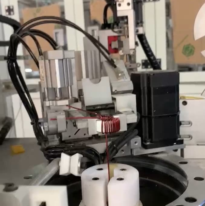
    Introduction In the competitive electronics industry, passive component manufacturers are constantly seeking ways to improve performance, reliability, and efficiency. One recent case demonstrates how the adoption of a 20×15×10mm nanocrystalline core not only met technical requirements but also delivered measurable business results. Background: The Customer’s Challenge A leading passive component manufacturer faced challenges with core efficiency and stability. Their existing solutions could not meet the growing demand for: Higher inductance in a compact size Lower energy losses Improved long-term reliability They needed a material that could deliver superior performance while maintaining cost-effectiveness. The Solution: Switching to a Nanocrystalline Core The customer decided to test a 20×15×10mm nanocrystalline core. This core, wound with high-quality copper wire, provided: High magnetic permeability for better inductance Low core losses at operating frequencies Compact size with strong performance The design change required minimal process adjustments, making integration smooth and efficient. Results: Measurable Business Impact The results were immediate and impactful: ✅ Enhanced product performance — Stable inductance and lower loss improved the customer’s final components. ✅ High customer satisfaction — End-users noticed the reliability, leading to positive feedback. ✅ Repeat orders — The customer reported continuous reorders after the switch. ✅ Profit growth — With stronger product competitiveness, profits increased by 5%. Customer Feedback The customer shared that the nanocrystalline core exceeded expectations: “By integrating the nanocrystalline core, our components gained a real edge in the market. Our clients are satisfied, and we’ve seen steady repeat business.” Why Choose Nanocrystalline Cores? This case illustrates the strategic value of nanocrystalline technology: 🌟 Higher efficiency compared to traditional ferrite or FeSiAl cores 🌟 Compact size without compromising performance 🌟 Proven reliability and durability 🌟 Direct business benefits — from customer trust to profit growth Conclusion The success of this 20×15×10mm nanocrystalline core application highlights the power of advanced materials in driving both technical and commercial results. For passive component manufacturers, adopting nanocrystalline cores can mean not just better performance, but also stronger customer loyalty and improved profitability.   👉 If you are looking for ways to enhance efficiency and gain a competitive advantage, nanocrystalline cores are a proven solution.
    Read More
  • Why Big Power Users Challenge the Grid – and How New Core Materials Provide the Answer
    Why Big Power Users Challenge the Grid – and How New Core Materials Provide the Answer
    Aug 18, 2025
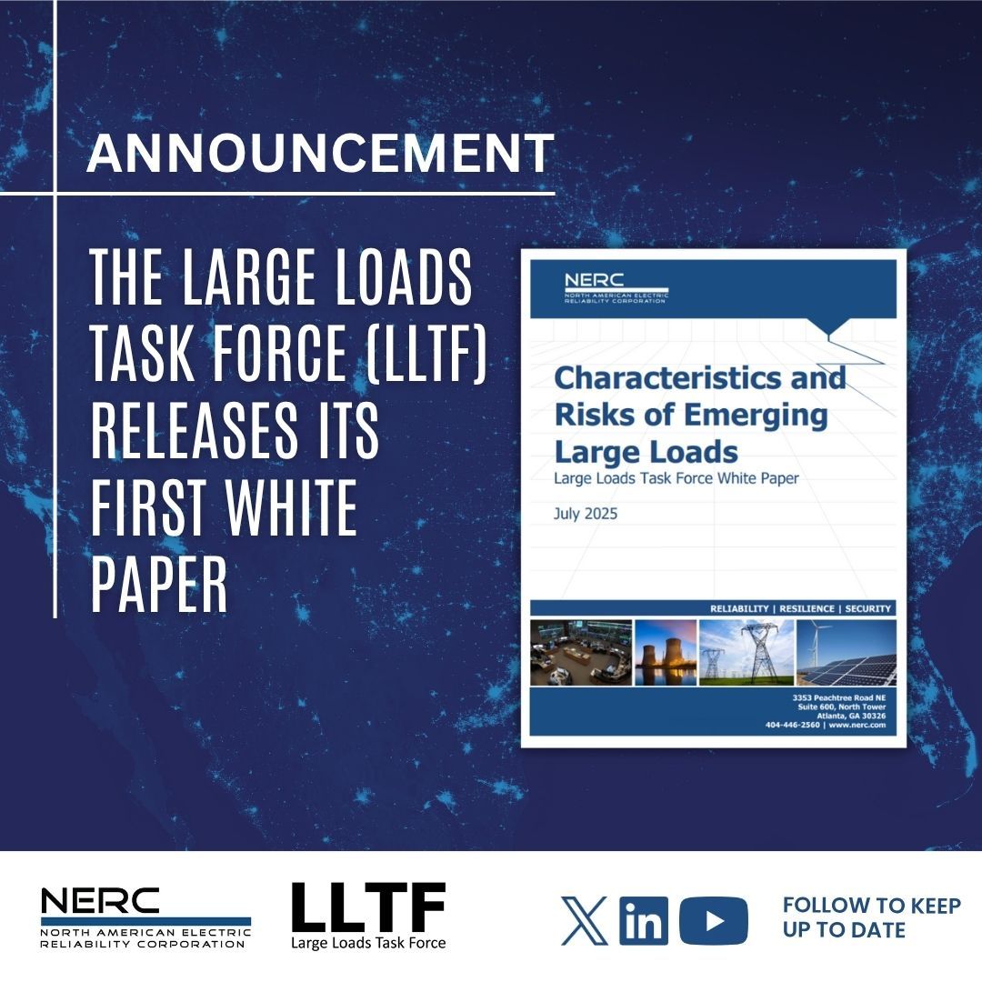
    Introduction Large energy consumers such as data centers, AI hubs, crypto farms, and hydrogen plants are changing the way electricity is used worldwide. These “mega-loads” bring economic growth but also create new risks for the power grid based on NERC white paper. This article explores: What problems these large loads create Why traditional transformers are not enough How amorphous and nanocrystalline cores provide the solution What Problems Do Emerging Large Loads Cause? 1. Harmonics – electrical noise Power electronics generate harmonics: unwanted signals that heat transformers, waste energy, and shorten lifespan. 2. Reactive Power – grid instability Cooling systems and drives cause reactive power that “pushes and pulls” on the grid, making voltage harder to stabilize. 3. Rapid Load Fluctuations AI clusters and mining rigs swing their demand suddenly, creating shocks for the grid. 4. Transformer Overheating Silicon steel transformers were never designed for these stresses. They overheat, fail early, and increase downtime costs. Why Are Traditional Transformers Not Enough? Traditional transformers are mainly built with silicon steel cores, a material that has served the grid reliably for decades. These designs were optimized for steady, predictable power flows—like lighting, motors, and household appliances. But the new reality is very different: Nonlinear loads: Data centers and crypto rigs don’t draw current in smooth waves. Instead, they create jagged, pulsed patterns that silicon steel cores struggle with. High core losses: When harmonics are present, silicon steel cores lose much more energy as heat. This not only wastes electricity but also drives up cooling needs. Shorter lifespans: Transformers overheat faster and age prematurely. This means more frequent replacements, higher maintenance budgets, and unplanned downtime. Grid mismatch: Traditional transformers cannot easily adapt to the fast fluctuations of AI clusters or renewable inputs like solar and wind. 👉 In short: the old designs were never made for the “digital” and “green” loads of today. What Are Amorphous and Nanocrystalline Cores? These are next-generation magnetic materials designed to meet modern grid demands. Instead of the crystalline structure of silicon steel, they have unique atomic arrangements that reduce losses and handle complex waveforms better. Amorphous cores Structure: Atoms are arranged randomly, not in a fixed crystal lattice. Benefit: This irregularity makes it much harder for magnetic domains to move, which drastically reduces energy lost as heat. Application: Best for distribution transformers where energy efficiency over 24/7 operation is critical. Nanocrystalline cores Structure: Extremely fine grains, on the nanometer scale, giving them unique magnetic softness. Benefit: Excellent performance at higher frequencies, strong resistance to harmonics, and stable under fluctuating loads. Application: Ideal for reactors, high-performance transformers, and power electronics in AI, EV charging, and renewable energy.   Together, these materials are redefining transformer design. They allow utilities and industries to cut losses by up to 70–80%, improve reliability, and prepare for the electrification and digitalization of everything—from AI to hydrogen. How Do These Materials Solve the Problem? Energy efficiency: Reduce wasted energy, supporting global carbon goals. Harmonic resilience: Keep transformers stable under noisy loads. Lower temperatures: Prevent overheating and extend lifespan. Green energy integration: Handle solar and wind variability smoothly. Applications in the Real World Data centers & AI hubs: High reliability with lower costs. Crypto mining & hydrogen plants: Avoid failures, improve ROI. Urban power grids: Reduce energy losses across entire networks. Conclusion Emerging large loads are reshaping electricity demand, but they don’t have to weaken the grid. With amorphous and nanocrystalline core technology, we can make power systems smarter, greener, and more resilient.   👉 Key takeaway: Advanced magnetic materials are no longer optional—they’re essential for the digital and renewable era.  
    Read More
  • Nanocrystalline Cores for EMI Suppression in EV Heater Systems – Design Guid
    Nanocrystalline Cores for EMI Suppression in EV Heater Systems – Design Guid
    Aug 14, 2025
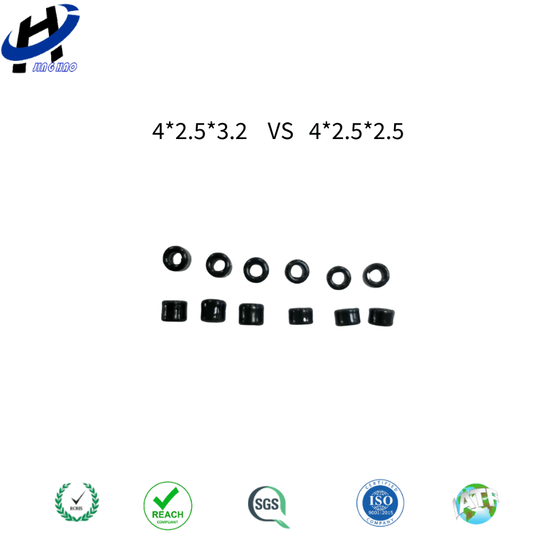
    In electric vehicle (EV) thermal management systems, the EV heater is a key high-voltage component. However, its switching operation and high power levels generate significant electromagnetic interference (EMI), which can impact overall electromagnetic compatibility (EMC) compliance.   Among available magnetic materials, iron-based nanocrystalline cores (such as FINEMET®, 1K107B) are increasingly popular for common-mode chokes (CMCs), current transformers, and localized magnetic shielding. Their high permeability, low loss, and thermal stability make them especially effective in specific EMI suppression scenarios.   When to Use Nanocrystalline Cores Dominant Common-Mode Noise (10 kHz – 5–10 MHz): Ideal for HV input lines and harnesses between EV heater, DC/DC converter, and OBC. High-Temperature Environments: Stable performance at 85–105°C. Compact Size Requirements: Smaller core size or fewer turns to meet impedance targets. Localized Magnetic Shielding: Tape-wound shields reduce leakage flux and radiated EMI.   When Not to Use (or Use with Caution) Differential-Mode Filtering/Energy Storage: Susceptible to DC saturation; better use gapped ferrite or powder cores. Very High Frequency EMI (>10–20 MHz): NiZn ferrite often more cost-effective. Harsh Mechanical Shock/Cost-Sensitive: Brittle and higher cost; requires careful mounting.   Typical EV Heater Applications HV+/HV− Common-Mode Choke Measure noise spectrum using LISN and CISPR 25 limits. Calculate impedance target and required inductance. Check leakage inductance, temperature rise, and saturation margin.   Harness Clamp-On Cores Installed close to noise sources or chassis entry points; affects only common-mode currents.   Localized Magnetic Shielding Wrap tape shields around noisy components; ground appropriately to reduce coupling.   Material Comparison Table Material μᵢ Range Bₛₐₜ (T) Frequency Strength DC Bias Tolerance Typical Uses Nanocrystalline 10⁴–10⁵ ~1.2 10 kHz–10 MHz Fair CMC, shielding, CT MnZn Ferrite 10²–10³ ~0.45 100 kHz–5 MHz Fair CMC, gapped energy storage NiZn Ferrite 10–10² ~0.35 5–100+ MHz Fair High-frequency suppression Powder Cores 10–100 0.8–1.5 Stable under DC bias Strong Differential-mode inductors   For more details about nanocrystalline core info., click https://www.amorphousoem.com/product/fe-based-1k107-42525mm-nanocrystalline-bead-for-spike-suppression
    Read More
  • The Power Filter Design Game Has Changed
    The Power Filter Design Game Has Changed
    Jul 23, 2025
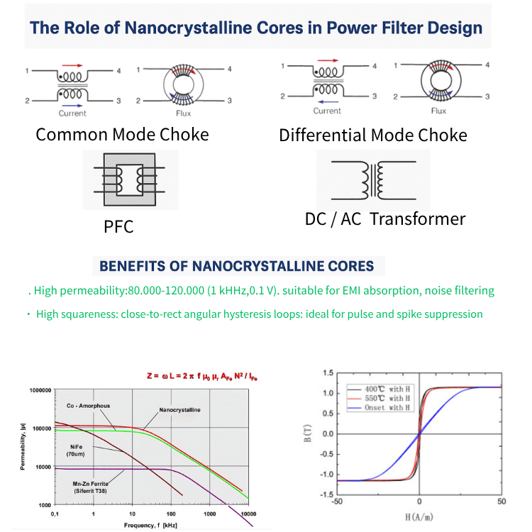
    With electric vehicles, solar inverters, and 5G power systems growing fast, one thing is clear: power filters are no longer optional. They're mission-critical.   EMI (electromagnetic interference) is a major headache in modern electronics. If you can’t control noise, you risk failing CE, FCC, or CISPR compliance — and losing the project.   So how is power filter design evolving? And why are more engineers switching to nanocrystalline magnetic cores?   Let’s break it down. 1. Why Power Filters Matter More Than Ever The global EMI filter market is expected to hit $1.5 billion by 2030 Nanocrystalline core demand is growing fast — from $1.3B in 2023 to $2.8B by 2030 EV charging stations, solar power, telecom power modules — all need compact, high-performance filters Designers must meet stricter EMC rules while shrinking size and boosting efficiency     2. What’s Changing in Power Filter Design ✅ Higher FrequenciesModern systems use SiC and GaN chips that switch at hundreds of kHz — even MHz. Ferrites can't keep up. ✅ Smaller FootprintDesigners want smaller filters, especially for EVs and telecom. You need materials that pack more power in less space. ✅ Tougher EMC RequirementsFilters now need 60dB+ noise reduction across 150kHz to 30MHz and beyond. ✅ Passing Certification Is HarderFailing EMC tests means delay, redesign, or lost business.     3. Why Nanocrystalline Cores Are the New Standard Feature Why It Matters Ultra-high permeability (80k–120k @ 1kHz, 0.1V) Absorbs EMI better, allows compact designs High squareness ratio (Br/Bs ≈ 1) Excellent spike and surge suppression Low core loss at high frequencies Runs cooler, saves energy Stable under heat Reliable even in harsh environments Helps meet EMC standards Easier CE/FCC/CISPR compliance       4. Where to Use Nanocrystalline Cores in Your Design 🔹 Common Mode ChokesPlaced on AC input to block common-mode noise→ Use toroidal nanocrystalline cores 🔹 Differential Mode FiltersPlaced after rectifiers or near outputs to block high-frequency switching noise→ Use gapped toroidal or cut cores 🔹 PFC InductorsPlaced in front of power factor correction stages to handle high current→ Use nanocrystalline C-cores or E-cores 🔹 Output Filters & TransformersPlaced near the load or in DC/DC converters→ Use custom-wound nanocrystalline cores     5. Real-World Advantages for Designers ✅ Reduce the number of filter stages✅ Shrink your filter size and weight✅ Improve system energy efficiency✅ Lower EMI and meet compliance faster✅ Design for tomorrow’s high-frequency needs — today     Ready to Try? Get Samples and Support Now We are an experienced OEM/ODM manufacturer of nanocrystalline and amorphous magnetic cores, serving customers worldwide in EV, inverter, power supply, and telecom industries. 🌐 Website: www.amorphousoem.com📩 Email: julia@amorphousoem.com📱 WhatsApp: +86 13686646827 💡 Contact us for:✅ Free sample kits✅ Filter design tips✅ Custom core manufacturing   Let’s engineer better filters — together.    
    Read More

leave a message

leave a message
If you are interested in our products and want to know more details,please leave a message here,we will reply you as soon as we can.
submit

home

products

WhatsApp

Contact