homepage
Leave A Message
If you are interested in our products and want to know more details,please leave a message here,we will reply you as soon as we can.
submit
banner
Home

JH Amorphous

JH Amorphous

  • Common Mode vs Differential Mode Choke: How to Split Roles in Power Supply EMI Filters
    Common Mode vs Differential Mode Choke: How to Split Roles in Power Supply EMI Filters
    Sep 30, 2026
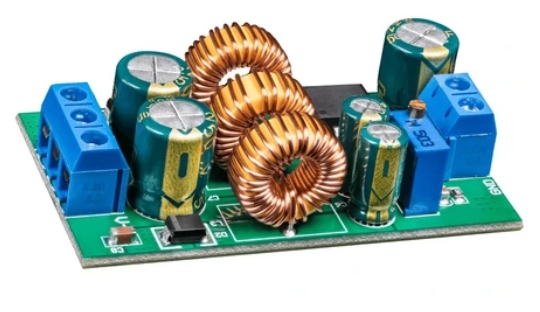
    How should CM and DM chokes split roles in the filter? A common mode choke (CMC) presents high impedance to noise currents that flow in the same direction on line and neutral (or on paired DC rails) while largely canceling flux for differential load current. A differential mode choke (DM choke) is an intentional series inductance in the power path that impedes normal-mode ripple and noise between the conductors. In power supply EMI filters you usually need both roles—often with X-capacitors for DM and Y-capacitors for CM—rather than forcing one part to do everything. Use high-μ nanocrystalline CMC grades for CM impedance at high current; use controlled-μ / gapped inductor-oriented cores for DM energy storage and ripple. For CMC sizing details, use JH’s published common mode choke selection guide. Why role splitting beats one big choke EMI failures mix CM and DM. Capacitor-only patches fail when inductance in the correct mode is missing. Conversely, oversized CMCs with huge leakage are sometimes asked to “also be the DM choke,” creating thermal, saturation, and radiated leakage problems. Role-split principles: Identify which mode fails on the LISN / EMC plot using separators, probes, or known X/Y sensitivity experiments. Assign CM impedance to a true CMC (closed-path, high μ, canceling windings). Assign DM impedance to DM inductors or to carefully budgeted CMC leakage—not accidental leakage alone. Match core grades to each role (avoid the μ trap). CMC role (pointer-style): CMCs suppress CM noise using high magnetizing inductance for in-phase currents. Iron-based nanocrystalline CMC cores typically offer Bs ~1.25 T, high initial μ (often ≈ 80,000–190,000 class for high-μ CMC grades), and stronger hot performance than ferrite that derates near ~100–120°C discussions, with finished assemblies often discussed from about −40°C to +140°C. Curie ~570°C for nanocrystalline alloys keeps the magnetic story viable when copper/plastics become the limiter. For step-by-step CMC selection (impedance band, current, AL, casing): see the published JH Common Mode Choke Selection Guide. This post does not rewrite that guide. CMC checklist: winding sense creates flux cancellation for DM current; lead dress stays tight to avoid turning the CMC into an antenna; imbalance and surge ampere-turns considered so μ does not collapse when you need it; temperature soak included in EMI proof. DM choke role: DM chokes see the full load current as magnetizing current (no cancellation). Therefore effective μ must be controlled so L holds under DC or low-frequency line current; gaps or distributed-gap strategies are common; fringing fields heat nearby copper and can radiate—manage winding placement; core loss and copper loss both matter at ripple frequencies. Use nanocrystalline or amorphous inductor-oriented grades—not a high-μ CMC anneal with an accidental gap. DM checklist: L at I_rms and I_peak; hotspot next to gap reviewed with thermal camera; acoustic whistle checked in light-load modes; interaction with X-caps for filter corner frequencies documented. How CM and DM share a filter—and how to diagnose Typical AC-input π / multi-stage filters: CMC + Y-caps → CM attenuation; DM inductors (or CMC leakage) + X-caps → DM attenuation; sometimes multiple stages for tough industrial / EV limits. Attribute Common mode choke Differential mode choke Current that magnetizes core CM noise / imbalance Load / ripple current Typical nanocrystalline grade High-μ CMC Low/controlled-μ inductor Cap partners Y-capacitors X-capacitors Main risk if wrong grade EMI fail, saturation on imbalance Saturation, heat, whistle Leakage fields Keep low via symmetry Inherent with gaps—manage Diagnostic flow when the scan fails: Does adding X-cap help more than Y-cap (or vice versa)? Points to DM vs CM dominance (with safety limits respected). Near-field probe on CMC vs gapped DM inductor—see open-path EMI signatures for leakage clues. Hot soak retest: ferrite CM parts may fade; nanocrystalline may hold CM impedance better magnetically. Check for mode conversion: poor wiring turns DM energy into CM on the cable. Only then change core materials or AL. Application patterns: EV charger—high line current, hot packaging; nanocrystalline CMC + dedicated DM choke on PFC is common (do not rely on CMC leakage alone). Industrial drives—long motor cables need line-side CMCs; do not double-count EMI and motor-protection inductors. Server PSU—split roles keep thermal and acoustic behavior predictable. Leakage inductance: CMC leakage can provide useful DM inductance in low-power filters. At high current, relying on leakage often means extra copper heating, radiated fields, and uncontrolled tolerance versus a designed DM choke. If you intentionally use leakage, specify and measure it; do not discover it in the EMC chamber. RFQ split language: CMC line: “High-μ nanocrystalline CMC core for CM impedance; target Z/L at ___ kHz; I_rms ___; case temp ___; see CMC selection guide parameters.” DM line: “Inductor-oriented core for DM choke; L at I_peak ___; f_ripple ___; gap policy ___; thermal hotspot limits ___.” Y-capacitors create touch-current / leakage budgets; you cannot endlessly “fix CM” with more Y—that is why CMCs matter. When leakage-current limited, invest in CMC impedance and wiring symmetry before proposing more Y capacitance. After a firmware change that alters light-load behavior, rerun a smoke EMI scan and a quick mic check near DM magnetics before freezing the filter BOM. JH Amorphous supplies CMC-oriented and inductor-oriented amorphous/nanocrystalline OEM cores (ISO9001:2015, IATF 16949)—quote as separate line items. Product starting point: nanocrystalline CMC cores. FAQ Q1: Can one nanocrystalline toroid serve as both CM and DM choke? Not optimally. Different grades and winding intents apply. Some filters use CMC leakage for DM, but high-power designs usually split parts. Q2: Why not use two DM chokes instead of a CMC? Without a CMC, CM impedance often relies on Y-caps and layout alone, which may fail limits or leakage-current budgets. CMCs remain the efficient CM tool. Q3: Does this replace the CMC selection guide? No. This article assigns roles. Use the published CMC selection guide for CMC sizing steps. Q4: Which fails first when grades are swapped? High-μ CMC used as DM → saturation/heat. DM core used as CMC → weak CM impedance and EMI fail. Related reading Common mode choke selection guide (CMC sizing) The μ trap: CMC grade vs inductor grade CMC inductor design: mounts, casing, impedance Nanocrystalline core for common mode choke If you need help splitting CM vs DM magnetics on a filter BOM, contact julia@amorphousoem.com — www.amorphousoem.com.
    Read More
  • Current Transformer Core Selection Guide: Amorphous, Nanocrystalline, and Accuracy Trade-offs
    Current Transformer Core Selection Guide: Amorphous, Nanocrystalline, and Accuracy Trade-offs
    Sep 29, 2026
    How do you pick amorphous vs nanocrystalline for a CT? Current transformer (CT) core selection starts from measurement or protection purpose, accuracy class, burden, frequency, and maximum current—including fault or inrush peaks that must not saturate the core if accuracy must hold. Amorphous and nanocrystalline cores are widely used in modern CTs because high permeability and favorable magnetics enable compact, low-ratio-error designs compared with older approaches—see also amorphous vs nanocrystalline for EVs/PV—while silicon steel remains common in some line-frequency protective CTs. Nanocrystalline often supports high accuracy and compact measuring CTs; amorphous is frequently chosen for specific cost/performance and protective or dual-purpose designs—always verify magnetization curves, remanence behavior, and temperature drift against your standard (IEC/IEEE accuracy classes). Pick the core for the CT’s accuracy and saturation story, not for CMC brochure μ (μ trap still applies if someone hands you a CMC datasheet). CT roles and material comparison CT intent What “good” means Core selection emphasis Measuring / metering Low ratio & phase error at rated burden High μ, low loss, stable vs temp Protective Accurate enough through fault currents; defined saturation Controlled saturation / remanence per standard Dual-purpose Compromise windows Explicit trade study Electronic / sensing Linearity in used range; SNR Small-signal behavior, noise OEM buyers for EV chargers, industrial drives, energy meters, and SST-like systems should state the intent in the RFQ. A metering nanocrystalline core and a protective CT core are not interchangeable by OD. Ratio error and phase displacement depend on magnetizing inductance (related to μ and geometry), winding resistance and leakage, burden magnitude and power factor, frequency and waveform (harmonics matter in power electronics), temperature, and remanence after asymmetrical faults (especially protection). High permeability reduces magnetizing current, which generally helps measuring accuracy—until remanence or saturation under asymmetrical currents becomes the limiting story for protection classes. Topic Amorphous CT cores Nanocrystalline CT cores Permeability / compactness Strong for many CT designs Very high-μ options; excellent for compact measuring CTs Loss / phase behavior Attractive in many line & mid-frequency uses Excellent for precision measuring in many OEM designs Saturation / remanence Grade & annealing dependent Grade dependent; widely used where high accuracy & size matter Temperature Alloy & finish dependent Alloy Curie ~570°C; finished part still limited by insulation/mechanics Buyer note Ask for magnetization & error curves Ask for error vs current & temp; do not use CMC datasheet alone Exact accuracy is a wound CT result, not a bare core miracle. Core suppliers provide magnetic properties; CT manufacturers validate class. Selection steps and failure modes Fix the standard and class. IEC 61869 family and related metering/protection classes define error limits. Write the class on the drawing before picking ribbon chemistry. Define current range. Rated primary, extended current, and fault levels. If the CT must not saturate at fault, protective requirements drive core area and magnetic knee behavior. Define burden and secondary. Burden resistors or relay inputs change error. Electronic burdens differ from classical relay burdens. Frequency and waveform. Power-electronics currents are not pure 50/60 Hz sine. Harmonics and DC components affect errors and saturation. Test with representative waveforms. Temperature. Automotive and outdoor energy products need −40°C class and hot ambient checks. Validate drift empirically. Mechanical and insulation. Window size for busbar, shielding needs, and hi-pot between secondary and core/case. Saturation and remanence: Measuring CTs optimized for tiny magnetizing current can retain flux after a fully offset fault, delaying accuracy recovery—critical in protection. Designers may use gapped or remanence-controlled cores for some protection classes. That is deliberate magnetic engineering, not a quality escape. Buyer question: “Is this core anneal intended for measuring, protective, or remanence-controlled protective use?” If the supplier cannot say, do not guess from μ alone. Power-electronics environments: Leakage fields from gapped inductors can couple into CT windows. High dv/dt can couple capacitively into secondary wiring—attend to shielding and cable practice. Heat from nearby magnetics shifts CT temperature and error. Place CTs with EMC and thermal maps in hand, not only CAD clearance. Data item Why it matters AL or μ at stated conditions Magnetizing behavior baseline Magnetization / BH related curves Saturation knee understanding Recommended for measuring vs protective Prevents misapplication Temperature notes Drift control Dimensional tolerances Turns and window fit Insulation / coating notes Safety and eddy control Traceability / QMS (ISO, IATF) Automotive & energy OEM needs Production notes: Lot AL sorting when CT designs are sensitive; avoid mixing CMC anneal lots into CT stock; control cutting/gapping if used for remanence control; protect cores from mechanical shock; document winding polarity and shield connections at the CT maker. Accuracy class is earned in process control as much as in alloy choice. If JH supplies cores and a third party winds CTs, freeze: core part number and magnetic grade description; incoming AL sampling plan; handling rules; shield and polarity drawings; final accuracy test ownership. Cite the applicable IEC 61869 (or regional equivalent) parts in RFQs, including extended current ratings and the actual secondary load network for electronic meters. DC components can saturate high-μ cores quickly—state DC presence in the RFQ. Silicon steel CTs remain common in some traditional protective applications; compare size, light-load accuracy, and loss/phase—not only price per kilogram. Dongguan JH Amorphous manufactures OEM/ODM amorphous and nanocrystalline cores under ISO9001:2015 and IATF 16949 and supports CT-oriented discussions separate from CMC high-μ marketing sheets. FAQ Q1: Is nanocrystalline always more accurate than amorphous for CTs? Not always. Many high-accuracy measuring CTs use nanocrystalline successfully, but the finished CT design, burden, and test conditions decide class. Compare curves for your use case. Q2: Can I use a high-μ CMC toroid as a CT core? Sometimes experimenters try; production CT designs need grades and validation aimed at accuracy and remanence behavior. Do not assume CMC stock is CT stock. Q3: How does temperature affect CT error? μ and dimensions drift; copper resistance changes with temperature. Validate across the product temperature range, including cold soak. Q4: What about DC tolerance? DC components can saturate high-μ cores quickly. Hall, fluxgate, or specially designed CTs may be required—state DC presence in the RFQ. Related reading Amorphous vs nanocrystalline selection for EVs/PV How core materials define CMC performance Nanocrystalline core for power applications High-temperature magnetics (temp drift context) For amorphous or nanocrystalline CT core selection against a stated accuracy class, send burden and current profile to julia@amorphousoem.com — www.amorphousoem.com.
    Read More
  • Precision at the Core: Why Nanocrystalline Ribbon Uniformity Defines High-Frequency Reliability
    Precision at the Core: Why Nanocrystalline Ribbon Uniformity Defines High-Frequency Reliability
    Mar 23, 2026
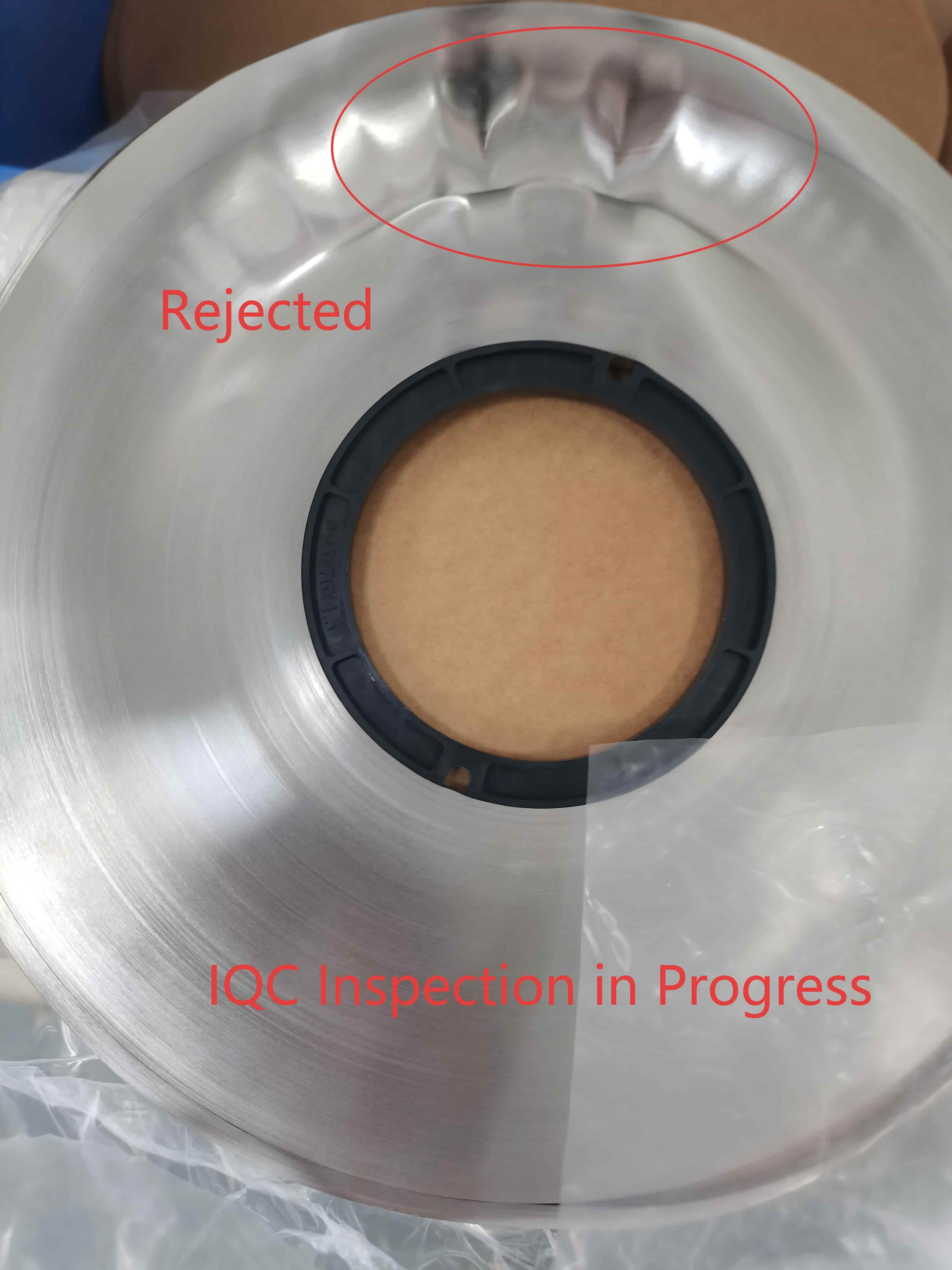
    In the precision-driven world of magnetic component manufacturing, what you can’t see often matters most. A roll of nanocrystalline ribbon might look like a sleek, metallic masterpiece to the untrained eye, but for the engineering team at JH Amorphous, a single "wave" or surface irregularity is a red flag that demands immediate action. Quality in power electronics doesn't begin on the assembly line; it begins at the atomic level of the raw materials we source. When we encounter a batch of nanocrystalline ribbon with uneven surface tension or "wavy edges," we aren't just looking at an aesthetic flaw—we are looking at a performance compromise that could jeopardize an entire high-frequency project.   The Physics of Flatness: Why Microns Matter   Nanocrystalline alloys are the backbone of modern high-power density inductors and transformers. Typically measuring between 12 and 20 micrometers—thinner than a human hair—these ribbons are remarkably sensitive to physical stress. Surface uniformity is not a luxury; it is a technical requirement for three critical reasons: 1. Optimizing the Stacking Factor: To achieve maximum magnetic efficiency in a compact footprint, ribbon layers must be wound as tightly as possible. Any "waviness" creates microscopic air gaps between layers. This reduces the stacking factor, leading to unpredictable eddy current losses and thermal spikes that can shorten the lifespan of a component. 2. Eliminating the "Acoustic Hum": In applications like EV charging or medical imaging, silence is a performance metric. Uneven layers within a core can lead to magnetostriction-induced vibrations. By rejecting ribbons with surface deviations, we prevent the dreaded "transformer hum" before the core is even wound. 3. Preserving Magnetic Permeability: Nanocrystalline materials are stress-sensitive. Mechanical tension caused by winding an uneven ribbon directly degrades magnetic permeability. This results in inconsistent EMI filtering and lower overall efficiency in power conversion.   The JH Amorphous Standard: An Uncompromising IQC Process   At JH Amorphous, our Incoming Quality Control (IQC) is designed to be the ultimate filter. We utilize high-precision metrology and surface profilometers to audit every batch of ribbon. If a material exceeds our rigorous flatness tolerance (often within ±2μm), it is immediately flagged and rejected. This level of scrutiny might seem obsessive, but it is the only way to ensure the reliability of the components that power renewable energy grids and electric vehicle drivetrains. By maintaining a strict feedback loop with our material suppliers, we ensure that only "Grade A" nanocrystalline ribbons enter our cleanrooms. This proactive rejection of sub-par materials is what allows us to deliver inductors that run cooler, quieter, and longer than standard market alternatives.   Engineering Reliability from the Core Up   The difference between a component that merely "works" and one that "excels" lies in the details that most manufacturers overlook. While others might attempt to compensate for poor material flatness by adjusting winding tension, we believe in solving the problem at the source.   Selecting the right magnetic component starts with selecting a partner who understands the material science behind the product. If your current prototypes are struggling with thermal management or acoustic noise, the root cause may be hidden within the layers of the core material itself.   Our engineering team is ready to help you optimize your next design with materials that meet your customized standard . Whether you are developing the next generation of SiC/GaN inverters or high-speed rail power systems, we invite you to explore how our commitment to raw material integrity can elevate your project’s performance.   Discover our range of high-precision magnetic solutions or reach out to our technical team to discuss your specific material requirements.
    Read More
  • 24MW SST Design: Why Nanocrystalline Cores are the Heart of High-Frequency Power
    24MW SST Design: Why Nanocrystalline Cores are the Heart of High-Frequency Power
    Mar 17, 2026
    The shift from traditional grid transformers to 24MW Solid State Transformers (SST) is driven by the need for extreme power density and efficiency. Converting 20kV to 0.8kV at a switching frequency of 30kHz requires more than just high-end semiconductors; it requires a breakthrough in magnetic material science. At JH Amorphous, we don’t just supply parts. When a client approaches us with a high-power design, our first engineering question is: "What is the topology for this component?" This allows us to tailor our nanocrystalline solutions to the specific stresses of your circuit.   The Architecture: 20kV ISOP & 30kHz DAB Scaling a system to 24MW requires a modular approach. The Input-Series Output-Parallel (ISOP) topology is used to manage the 20kV input by cascading 33 individual modules. Inside each module, the Dual Active Bridge (DAB) converter operates at 30kHz. At this frequency, the magnetic core is the primary bottleneck for thermal management. This is where JH Amorphous’s material expertise becomes the critical factor in system reliability.   Why Nanocrystalline is Mandatory for 24MW SST In a 727kW module, ferrite cores often reach their saturation limits too quickly, leading to massive heat spikes. Our Nanocrystalline cores provide a superior alternative: High Saturation Flux Density (Bs:1.25T ): Our materials handle higher power in a smaller footprint, reducing the overall size of the SST. Minimal Core Loss: At 30kHz, JH Amorphous nanocrystalline ribbons exhibit significantly lower losses than traditional silicon steel or ferrite, enabling the system to exceed 98.5% efficiency. Thermal Stability: Engineered for the demanding environment of 24/7 grid operation.   Precision Control & Engineering Logic A successful SST design is a "symphony" of hardware and software. We optimize our magnetic components to support: ZVS (Zero Voltage Switching): Minimizing switching stress on SiC MOSFETs. Balanced Power Flow: Our cores are manufactured with tight tolerances to ensure consistent performance across all cascaded modules in the CHB string. Optimized Winding: We provide design consultation on Litz wire and copper foil integration to maximize the benefits of our high-permeability materials.   Powering the Future of Grid Technology At JH Amorphous, we understand that an engineer is the soul of the product. Our goal is to provide the "magnetic backbone" for your most ambitious power electronics projects. Ready to optimize your 30kHz transformer design? Contact Julia at JH Amorphous for technical datasheets and custom core benchmarking.
    Read More
  • 2025 Year in Review: How JH Amorphous Reinvents Supply Chain Stability through Technical Upgrades
    2025 Year in Review: How JH Amorphous Reinvents Supply Chain Stability through Technical Upgrades
    Feb 14, 2026
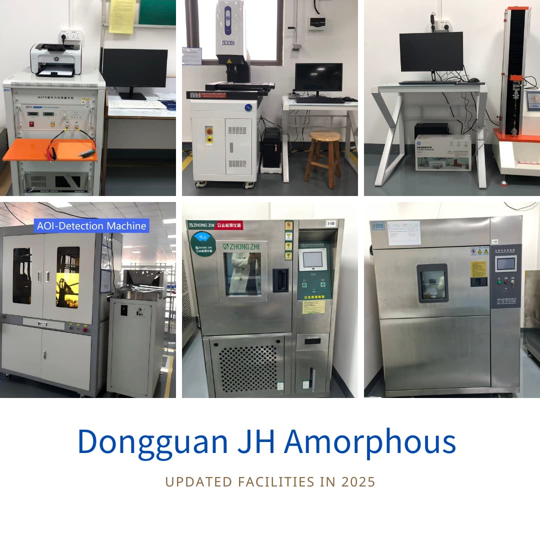
    Introduction: In manufacturing, growth isn’t an abstract feeling—it’s a measurable reality. As a senior partner once asked: "Before we renew the contract, tell me what has improved in your company this year." At Dongguan JH Amorphous Co., Ltd. (JH Amorphous), we answered that question in 2025 through physical expansion, massive R&D investment, and global market validation.   1. Capacity Expansion: Scaling for Global Demand To meet the rising global demand for high-performance amorphous and nanocrystalline solutions, we officially expanded our manufacturing facility this year. This expansion isn't just about square footage; it’s about optimizing lean production workflows. This strategic move has significantly boosted our output capacity while ensuring "just-in-time" delivery stability.   2. Quality Moat: Investing in State-of-the-Art Testing Quality is the DNA of JH Amorphous. In 2025, we integrated industry-leading testing equipment to transition from manual checks to smart, data-driven analytics: Static MATS Machine: For high-precision magnetic property analysis, ensuring peak electromagnetic consistency. Temperature & Humidity Chamber: Rigorous environmental stress testing to guarantee long-term reliability in diverse climates. Auto Video Measure Machine: Micron-level dimensional inspection to eliminate human error and ensure mechanical precision.   3. Global Reach: Strategic Growth in the USA, Europe, and Australia Our commitment to international compliance and technical excellence has led to a major breakthrough in high-end markets. This year, we secured several Tier-1 clients across the USA, Europe, and Australia. While strict NDAs protect their identities, their trust validates our position as a premier global OEM/ODM provider.   Closing Thoughts: In an uncertain world, "Stability is the ultimate growth." We strengthen our capabilities so that your supply chain remains bulletproof. As we look toward 2026, JH Amorphous remains dedicated to being your most reliable link in the power electronics industry.
    Read More
  • How Coating Affects Nanocrystalline Cores: Performance, Process, and Innovation | JH Amorphous
    How Coating Affects Nanocrystalline Cores: Performance, Process, and Innovation | JH Amorphous
    Oct 22, 2025
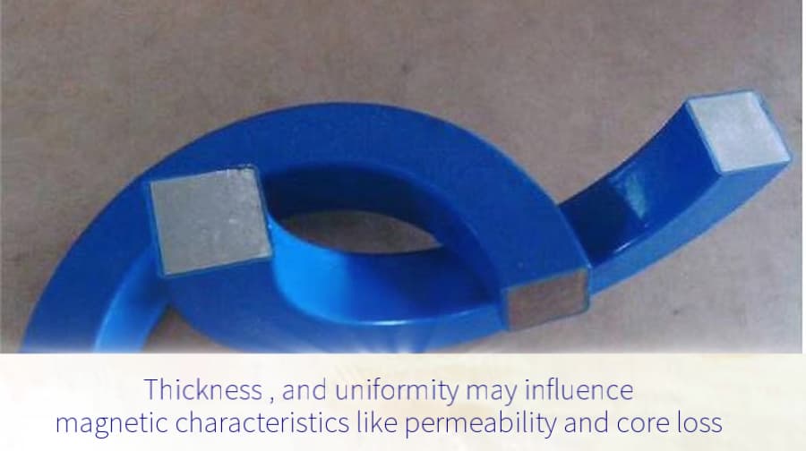
    Learn how coating impacts nanocrystalline cores in terms of performance, magnetic properties, and production efficiency. Discover how JH Amorphous optimizes coating technology for stability, cost-effectiveness, and innovation.   Nanocrystalline cores are essential in modern magnetic materials used in transformers, inductors, and other electronic devices. While their internal structure defines the magnetic properties, the coating applied to the core also plays a major role in determining performance, durability, and cost efficiency.   For high-quality nanocrystalline cores, coating materials must meet strict performance requirements. During the coating process, the layer should not create excessive stress that can damage the core. Once cured, the coating needs to offer high hardness, dimensional stability, good adhesion, insulation, and solvent resistance. These characteristics help maintain magnetic stability and ensure reliable performance throughout the product’s lifetime.   Because nanocrystalline cores often have ring-shaped structures, flexibility, and no chamfer, the coating process must be carefully selected. A dual-sided spraying method is often used to achieve uniform coverage across all magnetic surfaces, including edges and corners. This approach minimizes coating stress and prevents uneven thickness, which can lead to magnetic distortion or cracking. Proper control of parameters such as spray angle, coating viscosity, and curing temperature ensures both functional and aesthetic quality.   The coating also directly influences magnetic performance. Stress, coating thickness, and uniformity can all affect properties like magnetic permeability, core loss, and coercivity. Even small inconsistencies may cause changes in these parameters, reducing performance and efficiency. By optimizing coating parameters, manufacturers can minimize these effects and maintain stable magnetic characteristics. At JH Amorphous, advanced process control is used to ensure that every coating application supports the core’s intended performance.   Beyond performance, the coating process affects production efficiency and cost. Factors such as equipment speed, coating utilization, and material waste determine overall productivity. By optimizing these elements, JH Amorphous achieves higher throughput, lower waste, and more consistent quality. The result is a more efficient and sustainable manufacturing process that benefits both production and performance goals.   Continuous innovation is key to staying ahead in nanocrystalline technology. JH Amorphous continues to explore new coating materials and automated processes that enhance insulation, adhesion, and durability while maintaining environmental responsibility and cost-effectiveness. Through these efforts, the company delivers reliable and energy-efficient nanocrystalline cores that meet the evolving demands of global industries.     Coating may appear to be a small step in manufacturing, but it has a major impact on how nanocrystalline cores perform in real-world applications. Every layer counts — and with the right materials, processes, and innovation, coating becomes a crucial factor in achieving superior magnetic performance and long-term stability.   Video link:  https://www.amorphousoem.com/video/the-impact-of-coating-on-nanocrystalline-cores About Dongguan JH Amorphous Co., Ltd. Dongguan JH Amorphous Co., Ltd. is a professional manufacturer specializing in amorphous and nanocrystalline magnetic cores and parts.We serve industries including power electronics, renewable energy, automotive electrification, and industrial automation, offering both standard and custom magnet solutions. Contact Information:📧 julia@amorphousoem.com🌐 www.amorphousoem.com   Author:Julia YimInternational Marketing ManagerDongguan JH Amorphous Co., Ltd.
    Read More

leave a message

leave a message
If you are interested in our products and want to know more details,please leave a message here,we will reply you as soon as we can.
submit

home

products

WhatsApp

Contact