Apr 13, 2026
In modern power electronics, a "one-size-fits-all" common mode inductor simply doesn't exist. Every project brings a unique noise profile, mechanical constraint, and thermal limit. Designing an effective component requires balancing several moving parts: winding geometry, wire gauges, and core technology. To achieve optimal EMI suppression, you have to look at the inductor not just as a part, but as a complete system.
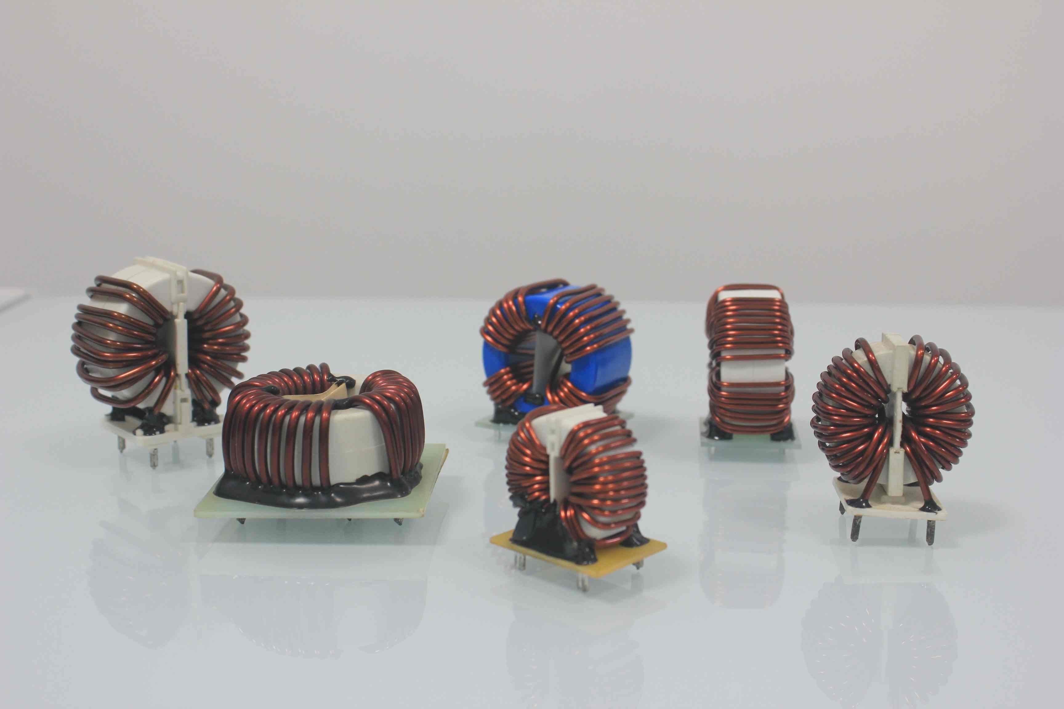
1. Structural Integration: Vertical vs. Horizontal Mounts
The physical orientation of an inductor is rarely a matter of preference; it is a strategic response to the specific geometry of your PCB and enclosure. In high-power density designs, spatial management is as critical as electrical performance.
• Vertical Mounts: These are the workhorses of high-density layouts. By utilizing the Z-axis, vertical inductors minimize the "real estate" occupied on the board. This is ideal for multi-component power stages where surface area is at a premium. However, the trade-off is height. You must ensure the component doesn't interfere with the chassis or create "dead zones" in the airflow path that could lead to localized hotspots.
• Horizontal Mounts: When restricted by a low-profile chassis—common in slim-line server racks or compact EV modules—horizontal mounts are essential. While they occupy a larger footprint, they keep the center of gravity low and provide better mechanical stability under high-vibration conditions.
The Rule: Lock in your orientation during the initial PCB floor-planning. Beyond physical fit, the core's orientation can influence magnetic coupling with nearby sensitive traces.
2. Encapsulation Strategy: Epoxy Coating vs. Plastic Casing
How the bare core is wrapped is a strategic decision between "power density" and "mechanical robustness."
• Epoxy Coating (The Slim Solution): This uses a micro-thin layer of insulation, offering minimal wall thickness. In space-constrained projects, a thinner coating allows for a larger bare core within the same footprint, maximizing impedance. It’s perfect for pushing the limits of volume, though it requires careful handling during assembly to avoid stress-induced performance shifts.
• Plastic Casing/Header (The Rugged Solution): For high-voltage environments or heavy industrial machinery, this "armor" is often non-negotiable. The casing provides a robust safety barrier and superior vibration resistance. While the plastic takes up more room—meaning the internal core must be slightly smaller—the gain in insulation and structural integrity is vital for safety-certified systems.
3. Impedance Optimization and Frequency Response
A common mode inductor’s effectiveness is a dynamic response to your circuit's specific noise profile. The goal is to hit peak impedance exactly where your switching noise is most aggressive, typically between and .
By leveraging nanocrystalline and amorphous materials, we can redefine the impedance-to-volume ratio. These materials offer significantly higher permeability across a broader spectrum than traditional ferrites. This means you can achieve superior noise suppression in a much smaller physical package. Always prioritize the impedance curve over a simple nominal inductance rating; a precision-engineered nanocrystalline core designed for your target frequency band will always outperform a generic high-inductance part.
4. Thermal Management and Wire Gauge Selection
Heat is the ultimate enemy of reliability. Selecting the right wire gauge is a trade-off between DC Resistance (DCR), current-carrying capacity, and winding limits.
• Passive Reliability: Most industrial designs rely on natural convection. We select wire diameters (typically 0.8mm to 2.0mm) to ensure the component remains "thermally invisible." This ensures that even under peak load, the inductor doesn't become a heat source that triggers thermal derating in nearby semiconductors.
• Engineering Rule: Never sacrifice wire gauge just to add more turns unless the magnetic benefit significantly outweighs the thermal risk. A cool-running inductor with slightly lower inductance is almost always more reliable in the field.
5. The Art of Winding Geometry
Winding is where theoretical design meets physical reality. The way the copper is laid down determines the actual high-frequency behavior of the part.
• Managing Parasitics: The inner diameter (ID) of the core limits how many turns you can fit in a single layer. Moving to a second layer increases parasitic capacitance, which can "choke off" high-frequency performance. Nanocrystalline cores help here—their high permeability allows you to reach target inductance with fewer turns, keeping the winding to a clean, single layer.
• Advanced Patterns: Winding geometry is a powerful tuning lever. For example, specific symmetrical patterns (like our "Style 2") consistently deliver higher impedance at high-frequency peaks. For heavy-duty industrial or EV power stages, we often utilize bifilar (parallel) winding to handle high current loads while maintaining thermal and magnetic equilibrium between the coils.
By integrating these five pillars—structure, encapsulation, material frequency response, thermal safety, and winding precision—you move beyond off-the-shelf limitations and build a power system that is both compliant and exceptionally reliable.
Read More


 Room 701, Jizhou Tongde Street 45, Shijie Town, Dongguan City, Guangdong Province, China
 +86-180 2701 0075
 sales@amorphousoem.com


 IPv6 network supported |
Sitemap
|
XML
|
blogs
|
Privacy Policy
IPv6 network supported |
Sitemap
|
XML
|
blogs
|
Privacy Policy