Dec 09, 2025
Engineering Insights into EMI Filters, PFC Chokes, and the Role of 1K107B Nanocrystalline vs. 1K101 Amorphous Cores
As power supplies for data centers and AI servers enter the 8.5 kW to 12 kW range, engineers face a significant architectural shift. Liquid cooling is becoming mainstream, switching frequencies are rising, and power density is pushing beyond 100 W/in³. These trends have brought a new bottleneck to the front of PSU design:
Magnetic materials — especially those used in EMI filters and PFC chokes — increasingly determine the feasibility of next-generation liquid-cooled power architectures.
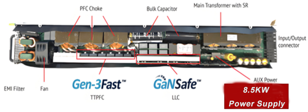
A commonly referenced teardown image of an 8.5 kW server PSU illustrates this point clearly:
EMI Filter positioned at the thermal entrance
PFC Choke (TTPFC) running at high frequency
Bulk Capacitors in the center
LLC stage and main transformer toward the cold plate regions
Compact mechanical layout optimized for liquid cooling
This configuration highlights a fundamental truth: when switching frequency increases and heat-spreading paths become constrained, magnetic core loss becomes the dominant thermal source in these front-end components.
1. Why Liquid Cooling Makes Magnetic Materials More Critical
Liquid cooling greatly improves heat extraction from power semiconductors (GaN, MOSFETs, SR devices). However, many magnetics — especially EMI filters and PFC inductors — are not mounted directly on cold plates.
In an 8.5 kW PSU:
The cold plate is reserved for semiconductors and key transformers
EMI and PFC inductors sit in restricted airflow zones
Their thermal paths are poorly coupled to the liquid cooling loop
This leads to an important engineering observation:
Magnetic components now rely far more on intrinsic core loss performance, rather than on mechanical cooling solutions.
As a result, differences between materials such as 1K107B nanocrystalline and 1K101 amorphous become significantly amplified.
2. The Rise of High-Frequency PFC: A Stress Test for Magnetic Materials
Typical PFC switching frequencies have increased from:
20–30 kHz → 40–70 kHz → approaching 100 kHz in TTPFC designs.
This shift improves power density but also raises:
AC flux density
Switching ripple
High-frequency harmonics
Core temperature
Because of this, the high-frequency loss curve becomes the dominant factor in magnetic selection.
Key Findings:
1K107B Nanocrystalline Core
Lower high-frequency core loss
More stable permeability
Better temperature behavior
Enables smaller inductors
Reduces hotspot temperature by 10–20°C in many PSU designs
1K101 Amorphous Core
Core loss increases steeply above 20–40 kHz
Larger physical size required
Higher hotspot temperatures
Less suitable for compact, liquid-cooled PSUs
In practice, many 6–8 kW PSU designs using 1K101 encounter either:✔ Excessive temperature rise✔ Oversized inductorsBoth of which limit system scalability.
3. Material Selection for EMI Filters in Liquid-Cooled PSUs
EMI filters are especially sensitive to high-frequency noise and temperature constraints. They require:
High permeability
Low HF loss
Surge robustness
Stable inductance under thermal stress
Nanocrystalline material (1K107B) offers advantages in:
Broadband EMI suppression
Maintaining inductance at elevated temperatures
Reducing size for compact front-end layouts
Lower incremental loss across switching harmonics
Therefore:
In modern 8.5 kW PSU designs, EMI filters increasingly favor 1K107B over 1K101.
4. Where Amorphous Material Still Excels
Despite the advantages of nanocrystalline cores in high-frequency stages, 1K101 amorphous remains the preferred material for:
Current transformers (CTs)
Low-frequency PFC input inductors
Large magnetic flux swing operations
HVDC filtering stages
High saturation flux requirements
This means:
The shift is not about replacing amorphous materials,but about using each material where it performs best.
5. Industry Trends: Migration Toward High-Frequency-Optimized Materials
Across major server OEMs and hyperscale power suppliers, engineering teams are converging on a clear material strategy for liquid-cooled PSUs:
✔ EMI Filter → 1K107B Nanocrystalline
✔ PFC Choke (TTPFC) → 1K107B Nanocrystalline
✔ Current Transformers → 1K101 Amorphous
✔ Input Inductors → Mixed (depending on ripple and frequency)
A shared viewpoint is emerging:
As PSU power density surpasses 100 W/in³,magnetic material selection becomes just as critical as topology selection.
🗣️ Discussion: What Will Be the Next Bottleneck?
As server PSUs evolve from 8.5 kW → 10 kW → 12 kW, liquid cooling and GaN technologies will continue to push the boundaries of power density. But magnetics remain key thermal contributors — especially in front-end EMI and PFC stages.
A question for engineers designing next-generation AI server PSUs:
Which magnetic component do you expect to become the next limiting factor in ultra-dense liquid-cooled designs?
EMI choke?
TTPFC inductor?
LLC transformer?
Or the magnetic materials themselves?
Your insights and field experiences are welcome.
Read More

 Room 701, Jizhou Tongde Street 45, Shijie Town, Dongguan City, Guangdong Province, China
 +86-180 2701 0075
 sales@amorphousoem.com


 IPv6 network supported |
Sitemap
|
XML
|
blogs
|
Privacy Policy
IPv6 network supported |
Sitemap
|
XML
|
blogs
|
Privacy Policy