
Leave A Message
If you are interested in our products and want to know more details,please leave a message here,we will reply you as soon as we can.


The μ Trap on Nanocrystalline Datasheets: High-μ CMC Grades vs Low-μ Power Inductor Grades
Nanocrystalline datasheet permeability is not one number for every design. High-μ CMC grades (μ ≈ 80,000–190,000) are finished for common-mode impedance with minimal intentional gap. Low-μ power inductor grades use controlled shear, gap, or process tuning so L stays linear under DC bias. Swap the grades and you get early saturation, wrong AL, whistle, or EMI fail. Read Bs (~1.25 T iron-based nano), μ or AL at stated frequency and excitation, DC-bias curve, and temperature notes before freezing the BOM. Match grade to function first; size second.
Most RFQs arrive with a μ screenshot and a target L. That looks efficient—and incomplete.
μ on a nanocrystalline datasheet is usually measured on a specific test geometry, at low AC excitation (often millitesla), at a stated frequency (commonly ~10 kHz), and without the DC bias your power stage applies.
A “μ = 90,000” CMC row can be true at small signal and still useless for a PFC boost inductor at several amperes DC. A controlled low effective-μ inductor grade—often discussed in the ~200–600 range for some power inductor families, grade-dependent—can look weak next to a CMC sheet until you overlay the bias curve. Then L holds where the high-μ part has already collapsed.
At Dongguan JH Amorphous we see this weekly from EV charger, industrial drive, and server PSU teams (same failure mode as our Italian OBC and German 800 V filter cases): the mechanical drawing matches, the ribbon chemistry is nanocrystalline, yet the finished choke fails because the magnetic grade was chosen from the wrong column.
| Intent | Finishing | Optimize | Failure if mismatched |
|---|---|---|---|
| CMC | High initial μ, closed path | Z_cm over EMI band, few turns | Saturates on imbalance; EMI collapses |
| Power / DM inductor | Lower effective μ via process/gap | AL under DC bias, linear L | Excess Im, hot copper, whistle |
| CT / sensor | Accuracy-oriented grade | Ratio/phase error, temp drift | Metering error, mis-trip |
“High” and “low” are relative to the envelope, not a ranking.
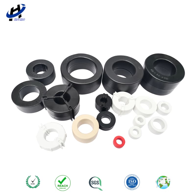
High-μ CMC grades usually ship as closed-path cased toroids—read μ with the finishing route, not as a universal ranking.
High-μ CMC typical ranges we support: Bs ≈ 1.25 T (Mn-Zn ferrite ≈ 0.4 T); initial μ often ≈ 80,000–190,000; finished case window commonly −40°C to +140°C; Curie ≈ 570°C—so thermal μ collapse is not the ferrite near-100°C story.
How to read a high-μ row: confirm measurement frequency (EMI cares about impedance from ~150 kHz up); ask for AL (nH/N²), not only μ; request DC-bias or imbalance notes; check casing and ribbon insulation for automatic vs hand winding. High-μ is the right tool for broadband CM impedance at high line current with limited copper budget. It is the wrong tool for storing energy under DC bias.
Low-μ / inductor grades deliberately reduce effective μ so the B–H loop stays usable under ampere-turns, ½LI² is predictable, and fringing can be managed by gap/process choices. Comparing that μ to a CMC datasheet without the bias column makes the inductor grade look inferior. In the power stage it is often superior.
Inductor checklist: AL vs DC bias at I_peak and I_rms; core loss density at f_sw and ΔB; fringing/hotspot guidance if discrete gap; magnetostriction risk in the audio band; thermal derating of copper and case, not only Curie.
Rule of thumb: if the part must store energy or hold L under DC, start from the inductor-grade family and verify bias. If it must present CM impedance with canceling ampere-turns, start from the high-μ CMC family and verify EMI-band impedance.
| Parameter | High-μ CMC | Low-μ inductor |
|---|---|---|
| Small-signal μ / AL | Very high | Moderate / controlled |
| First use | CM EMI choke | PFC / DM / energy storage |
| DC bias tolerance | Saturates earlier in ampere-turns | Designed to hold L under bias |
| Risk if swapped | Inductor saturates; overheating | CMC underperforms; EMI fail |
One OD for both roles is fine only after both grades are qualified on their own curves.
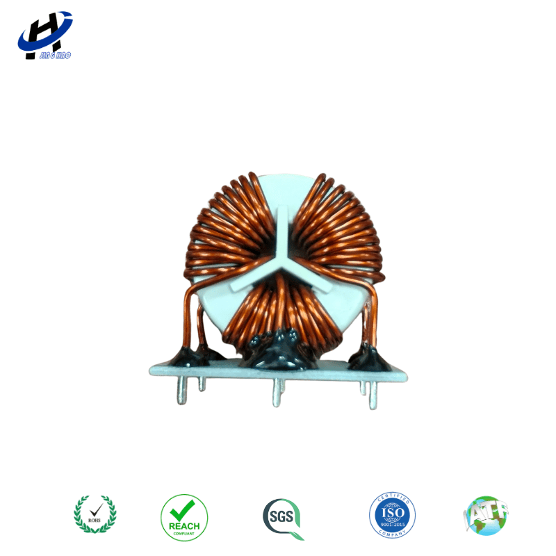
Wound CMC example: ampere-turn cancelation depends on the high-μ grade; the same OD in an inductor finish behaves differently under DC bias.
Replace “need μ > 80k” with a function-led RFQ.
CMC cores: application (1-phase / 3-phase / DC); target Z_cm or L_cm at stated frequency points; I_rms, I_peak, expected imbalance; ambient/case target; OD/ID/HT, case material, UL/RoHS; preferred AL range plus impedance or sample insertion-loss data.
Power inductor cores: topology and f_sw; L at I_sat and I_rms; ΔB / loss budget; acoustic limits if any; gap policy and winding window; preferred AL vs DC bias plus loss data.
Questions that expose the trap early: Is this quoted from a CMC finishing route or an inductor route? At what H (or ampere-turns) was μ measured? Do you have AL at my DC bias? Is ribbon insulation rated for my winding process?
Practical notes: high-μ permeability still falls with frequency—use impedance vs frequency of the wound choke. High μ reaches a given B with less H, so unintended DC can saturate a CMC earlier than a lower-μ part of similar Ae. Ask for lot AL tolerance and sort method on OEM builds.
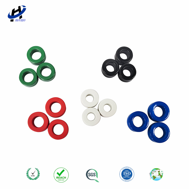
Coated nanocrystalline family—match AL / bias / impedance curves to the function column on the datasheet.
No. Higher μ helps common-mode chokes that need high L with few turns at low bias. Power inductors usually need controlled lower effective μ so inductance survives DC bias.
Mechanically sometimes; magnetically only if you select the correct finishing grade for each role and qualify both. Sharing OD without sharing grade is how the μ trap enters the BOM.
Many high-μ CMC grades fall around ≈ 80,000–190,000 depending on grade and test conditions. Confirm AL, bias behavior, and impedance vs frequency rather than locking a single brochure μ.
Likely early saturation under DC ampere-turns, excess magnetizing current, and copper loss—sometimes plus fringing if gapped. Move to an inductor-oriented grade and re-check AL vs bias and loss.
If a datasheet μ row looks ambiguous for your CMC or inductor RFQ, email julia@amorphousoem.com with topology, current, temperature, and target L or Z_cm — www.amorphousoem.com.
 Room 701, Jizhou Tongde Street 45, Shijie Town, Dongguan City, Guangdong Province, China
 +86-180 2701 0075
 sales@amorphousoem.com


 IPv6 network supported |
Sitemap
|
XML
|
blogs
|
Privacy Policy
IPv6 network supported |
Sitemap
|
XML
|
blogs
|
Privacy Policy