Sep 28, 2026
Which cores sit inside an SST power stage?
Solid state transformer (SST) magnetic components are the high- or medium-frequency transformers, filter inductors, and EMI chokes that enable power conversion stages to replace bulky line-frequency magnetics. Inside an SST, cores see elevated switching frequencies, multilevel or modular converter stresses, isolation requirements, and thermal density that differ from 50/60 Hz distribution transformers. Nanocrystalline and amorphous alloys often appear in medium-frequency transformers and high-performance filters because of favorable loss/size trade-offs and high Bs (~1.25 T class for iron-based nanocrystalline vs ~0.4 T ferrite), while ferrite remains relevant in some higher-frequency, lower-flux niches. Specify cores by stage function—isolation transformer, link inductor, or CMC—not by a single “SST alloy” slogan.
SST magnetics by stage role
From a magnetics desk, SST architecture usually breaks into:
Input stage — AC/DC or multilevel conversion with line filters (CMCs, DM inductors)
Isolation stage — medium/high-frequency transformers (the heart of size reduction)
Output stage — inversion or DC ports with additional filter magnetics
Auxiliary magnetics — gate-drive transformers, sensors/CTs, snubber inductors
Each block has different flux, frequency, and insulation demands. Buying “one core material for the SST” is how programs stall. JH has already published focused content on SST size-versus-heat at 50 kHz and a 24 MW SST nanocrystalline architecture note; here we map component roles and core selection questions so OEM buyers and applications engineers share vocabulary when requesting samples.
Isolation / medium-frequency transformer checklist: target frequency band and waveform (square, quasi-square, multilevel); voltage-second product and ΔB budget; isolation voltage, partial discharge, creepage/clearance on the finished winding; thermal path (oil, air, cold plate, potting); mechanical geometry suited to the winding scheme.
Material family
Typical SST-leaning role
Watch-outs
Nanocrystalline
Medium-frequency isolation & high-performance filters
Ribbon insulation, cutting, AL control
Amorphous
Competitive loss/size in defined bands
Noise, cutting, grade selection
Ferrite
Higher frequency / lower flux designs
Temp derating near ~100–120°C class; Bs ~0.4 T
Silicon steel
Lower frequency / large power traditional
Not the SST miniaturization story
Nanocrystalline Curie ~570°C helps magnetically at elevated temperature; finished systems still face copper and insulation limits. SST insulation systems may differ from PSU case windows (-40 to +140°C discussions elsewhere) and must be specified explicitly.
Filter inductors and link magnetics: Boost / buck / resonant tank inductors depending on topology; DM chokes on AC ports; CMCs for EMI against grid codes. Inductor cores should be inductor-oriented grades with AL vs DC bias honesty—not high-μ CMC grades pressed into energy storage (the μ trap). Gapped designs need fringing hotspot discipline for copper near gaps.
Grid-connected SSTs face strict harmonic and EMI expectations. High-μ nanocrystalline CMC grades (often ≈ 80,000–190,000 class) help when high current and strong low-frequency CM impedance are required. Complement—not rewrite—your CMC selection process: size by impedance band, current, and temperature.
Cut nanocrystalline C-cores appear in SST isolation and high-frequency transformer stages.
Stresses, comparison, and RFQ discipline
SST modules may see fast dv/dt from SiC/GaN stressing insulation; common-mode voltages across isolation transformers; uneven module loading in cascaded architectures; wide ambient in outdoor energy cabinets. Core RFQs should include insulation system questions (ceramic vs organic ribbon themes), hi-pot strategy, and thermal mapping—not only Ae and AL.
Stage magnetics
Primary job
Core selection focus
Failure if mismatched
MF/HF isolation transformer
Energy transfer + isolation
Loss vs f, ΔB, insulation
Overheat, PD, bulk
Link / filter inductor
Energy storage / ripple
AL under bias, fringing
Saturation, hot copper
Line CMC
CM EMI impedance
High μ, current, temp
EMC fail when hot/loaded
CT / sensors
Measurement
Accuracy, burden, temp
Control error
Gate-drive transformer
Isolation for gates
Capacitance, creepage
Shoot-through risk
Thermal and mechanical: Measure winding and core temperatures under worst multilevel patterns—not only sinusoidal lab excitation. Magnetostriction audible noise can appear in outdoor installations. Vibration in mobile or trailer-mounted systems needs impregnation and mount control. Do not assume liquid cooling of semiconductors cools every magnetic component equally.
RFQ template: “Component role: [MF transformer / CMC / DM inductor / CT]. Topology frequency ___ kHz; waveform notes ___; voltage-second or L(I) targets ___; isolation voltage ___; ambient/hotspot ___; cooling method ___; preferred alloy family ___; documentation (ISO/IATF) ___; annual volume ___.”
Development sequence: Freeze architecture frequencies and modularity → allocate loss budgets per magnetic component → select materials per role and prototype transformers and filters separately → integrate EMI early (SST cabinets are excellent antennas when leakage is ignored) → only then optimize cost with tooling and PPAP if automotive-adjacent. Skipping EMI early creates late shields and capacitor banks that erase earlier size wins.
Appoint a magnetics owner who translates volt-seconds into ΔB and Ae candidates, isolation specs into winding/core insulation asks, cabinet airflow into hotspot limits, and EMC pre-scan results into CMC vs DM actions. In modular SSTs, shared AC-port CMCs see aggregated EMI of many cells—undersizing them is a common system mistake when each cell team only budgets “its own” noise. Tag each BOM line with role and grade family so warehouse staff cannot interchange parts by OD.
Dongguan JH Amorphous supplies OEM/ODM nanocrystalline and amorphous cores (ISO9001:2015, IATF 16949) for energy and industrial power electronics teams building SST-like architectures.
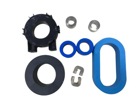
SST magnetics mix closed toroids and cut cores depending on energy storage vs isolation needs.
Filter-stage wound magnetics: size by role (CMC vs DM), not by a single SST alloy slogan.
Closed-path toroids for CM filtering alongside cut cores for isolation stages.
FAQ
Q1: Is nanocrystalline always required for SST transformers?
No. It is a strong candidate for many medium-frequency designs, but frequency, voltage, and cooling can favor other families. Compare loss and insulation readiness.
Q2: Can ferrite SST transformers work at high power?
Sometimes at higher frequency and carefully managed flux/temperature. Bs ~0.4 T and thermal derating near ~100–120°C class behavior limit some dense designs.
Q3: Do SSTs still need common mode chokes?
Usually yes at AC interfaces and often on other ports. Electronics do not remove EMI physics.
Q4: What is the first datasheet trap in SST magnetics buying?
Using CMC high-μ permeability rows to specify power inductors or transformers without loss and bias data.
Larger core windows for higher power SST stages—loss density and cooling paths dominate sizing.
Related reading
Engineering the 50 kHz SST size-vs-heat trade-off
24 MW SST design with nanocrystalline cores
Amorphous vs nanocrystalline for EVs and PV
High-power nanocrystalline cut C-core
If you need OEM core samples by SST stage role, email julia@amorphousoem.com with frequency, isolation, and thermal targets — www.amorphousoem.com.
Read More


 Room 701, Jizhou Tongde Street 45, Shijie Town, Dongguan City, Guangdong Province, China
 +86-180 2701 0075
 sales@amorphousoem.com


 IPv6 network supported |
Sitemap
|
XML
|
blogs
|
Privacy Policy
IPv6 network supported |
Sitemap
|
XML
|
blogs
|
Privacy Policy